Blade shroud vibration monitor

a vibration monitor and shroud technology, applied in the direction of instruments, liquid fuel engines, static/dynamic balance measurement, etc., can solve the problems of blades being excited by non-synchronous forces, and affecting the operation of the machin

Active Publication Date: 2008-08-28
SIEMENS ENERGY INC
View PDF21 Cites 56 Cited by
  • Summary
  • Abstract
  • Description
  • Claims
  • Application Information

AI Technical Summary

Problems solved by technology

Due to their complex design, natural resonant mechanical frequencies of the blades may coincide with or be excited by certain blade rotational speeds and rotational harmonics thereof.
However, the blades may be excited by non-synchronous forces such as aerodynamic buffeting or flutter.
When the amplitude of the vibration exceeds a certain level, objectionable stresses are set up in the blade.
If the condition is not detected and remedied, the blade may eventually fracture resulting in extensive damage, thus shutting the machine down and requiring a costly forced outage for exte

Method used


Image

  • Blade shroud vibration monitor
  • Blade shroud vibration monitor
  • Blade shroud vibration monitor

Examples


example 1

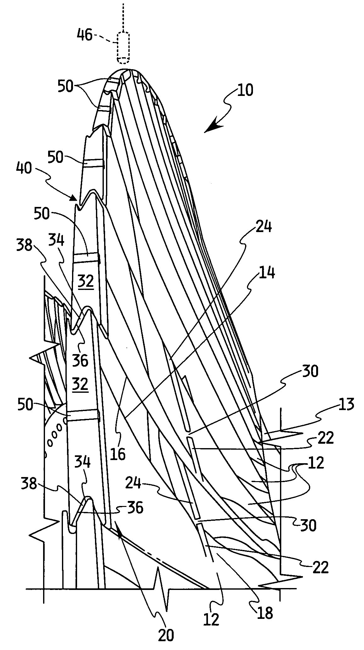
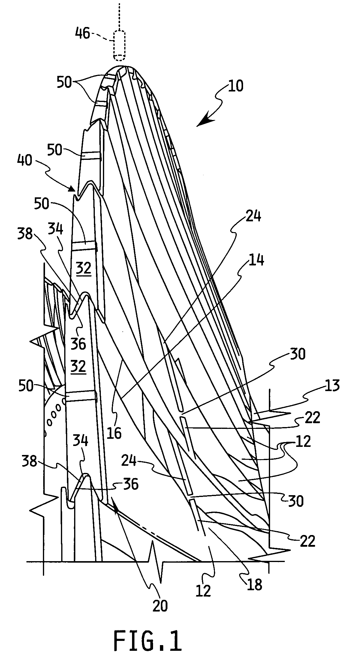
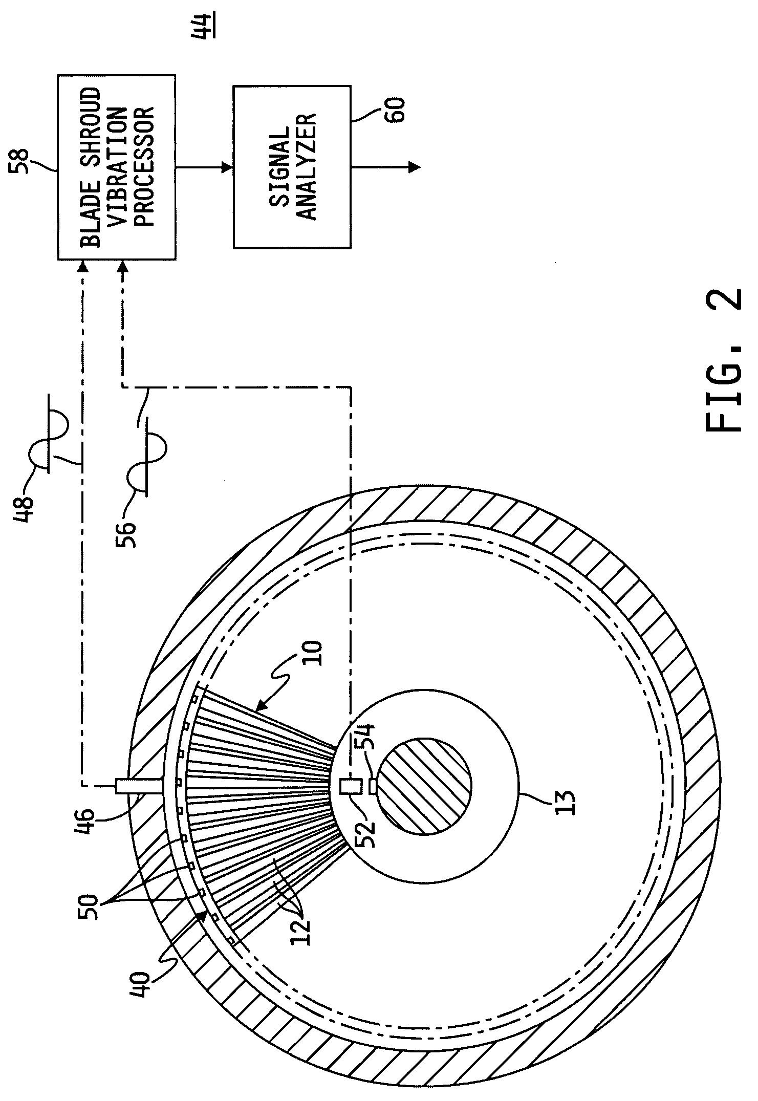
[0049]Referring to FIGS. 4-6, a first comparison of an analysis provided by the BSVM system is shown relative to an analysis of the same data provided by the BVM system for a first event. The data is based on a test performed on a shrouded steam turbine blade row. Steel targets 50 were wedged into the outer surface of fifty-eight titanium shroud portions 32 corresponding to fifty-eight equally spaced blades 12, and a single magnetic reluctance probe was used to provide signals corresponding to the actual arrival time of the targets 50. The blade row was rotated at a speed of 3600 rpm, corresponding to a rotational frequency of 60 Hz.

[0050]FIG. 4 shows the BVM measured amplitude for each of the 58 targets (blades) based on the measured 6th BVM subharmonic. FIG. 5 shows a 16 line BVM spectra (average of all blades) with 1.875 Hz resolution for the first event, in which the 6th and 11th subharmonics appear responsive, i.e., indicate a peak shroud vibration wave. The spectra for the BVM...

example 2

[0052]Referring to FIGS. 7-8, a comparison of an analysis provided by the BSVM system is shown relative to an analysis of the same data provided by the BVM system for a second event, using the same setup as described for Example 1.

[0053]FIG. 7 shows a 16 line BVM spectra with 1.875 Hz resolution for the second event, in which the 6th subharmonic is shown as clearly appearing responsive. However, in the BSVM analysis of the same data, as shown in FIG. 8, it can be seen that both the 58th and 134th subharmonics are responsive which, in the BVM analysis, fold onto the 0 to 30 Hz spectral range, and which combine as a vector sum to appear as the 6th subharmonic. In addition, the BSVM analysis illustrated in FIG. 8 shows further spectral lines at subharmonics of 43 Hz, 73 Hz, 77 Hz, 103 Hz, 179 Hz, and 223 Hz, as noted along with the corresponding folded down BVM subharmonics that result from an analysis of the blade vibrations taken individually.

[0054]From the above description, it can ...


PUM


Abstract

A method for predicting a blade structure failure within a coupled blade structure including a plurality of blades supported for rotation on a rotor and a shroud structure coupling the blades. The method includes the steps of determining displacements of a plurality of predetermined circumferential locations on the shroud structure during rotation of the blade row, where the displacements are provided as a function of time relative to the periodic rotation of the shroud structure for time intervals that are integer multiples of rotor rotation. A signal characteristic related to vibrational mode and a nodal diameter of the shroud structure is derived based on the displacements of the circumferential locations on the shroud structure.

Description

FIELD OF THE INVENTION[0001]The present invention relates to monitoring the vibrational characteristics of a rotating blade row and, more particularly, to a method of analyzing the vibrational characteristics of a consolidated unitary blade structure comprising a rotating row of blades and a circumferential shroud coupling the blades.BACKGROUND OF THE INVENTION[0002]A high speed turbo machine, such as, for example, a steam or gas turbine, generally comprises a plurality of blades arranged in axially oriented rows, the rows of blades being rotated in response to the force of a high pressure fluid flowing axially through the machine. Due to their complex design, natural resonant mechanical frequencies of the blades may coincide with or be excited by certain blade rotational speeds and rotational harmonics thereof. Each natural frequency is associated with a particular mode, each of which is a different combination of vibrational deflections such as along the rotational axis of the tur...

Claims


Application Information

Patent Timeline
IPC IPC(8): F01D5/10
CPCG01H1/006F01D5/225
Inventor TWERDOCHLIB, MICHAEL
Owner SIEMENS ENERGY INC
Why Eureka
Try Eureka