Magnetic coupling and camera platform using magnetic coupling

a technology of magnetic coupling and camera platform, which is applied in the direction of couplings, slip couplings, instruments, etc., can solve the problems of difficult to perform precise control, and difficult to completely prevent the occurrence of phase differences. , to achieve the effect of enabling damping vibrations, enabling precision control, and maintaining silencing performan

Inactive Publication Date: 2008-08-28
CANON KK
View PDF2 Cites 22 Cited by
  • Summary
  • Abstract
  • Description
  • Claims
  • Application Information

AI Technical Summary

Benefits of technology

[0009]The present invention is directed a magnetic coupling that enables damping vibrations occurring at the magnetic coupling while maintaining a silencing performance unique to the magnetic coupling without complex configuration, and also enables precision control by reducing a phase difference. The present invention is also directed to a camera platform using the magnetic coupling.

Problems solved by technology

The magnetic coupling, however, may cause a phase difference in rotation between the drive shaft and the driven shaft since the magnetic coupling transmits power in a non-contact manner.
Although the method discussed in Japanese Patent Application Laid-Open No. 07-111772 generates a supporting force in the circumferential direction in a neutral position and reduces the occurrence of a phase difference, it is difficult to completely prevent the occurrence of a phase difference because the magnetic coupling uses a non-contact type power transmission.
It is also difficult to perform precise control, according to Japanese Patent Application Laid-Open No. 07-111772, since no method is available for damping a vibration itself occurring in the circumferential direction.
Although the method discussed in Japanese Patent Application Laid-Open No. 11-013855 enables quickly damping vibrations of the driven shaft in the circumferential direction by performing feedback control of a source of power based on an output from the detecting unit, the method requires a complex configuration to perform feedback control.

Method used


Image

  • Magnetic coupling and camera platform using magnetic coupling
  • Magnetic coupling and camera platform using magnetic coupling
  • Magnetic coupling and camera platform using magnetic coupling

Examples


first exemplary embodiment

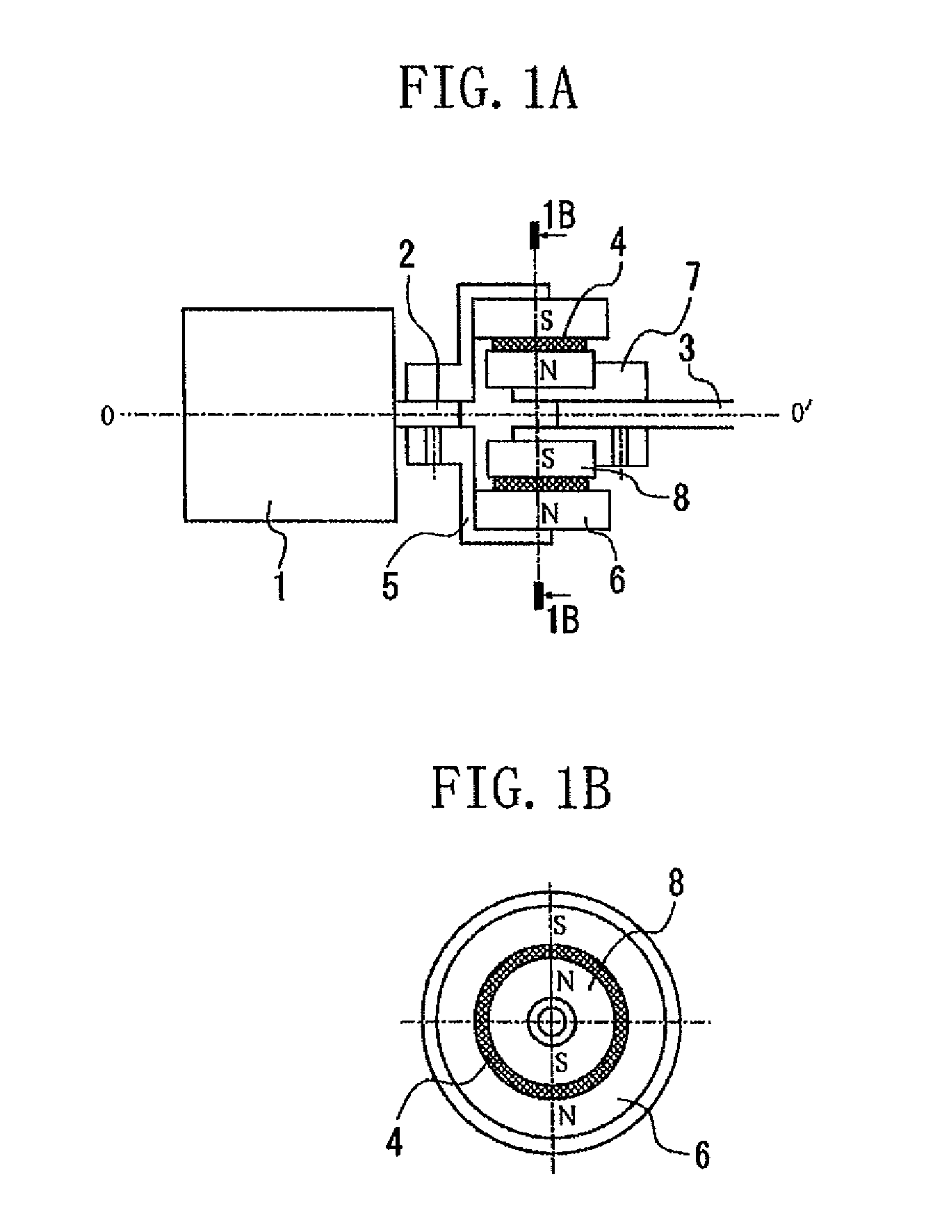
[0020]FIGS. 1A and 1B illustrate a configuration of a magnetic coupling according to a first exemplary embodiment of the present invention. FIG. 1B is a cross-sectional view taken along line 1B-1B in FIG. 1A.

[0021]A motor 1, acting as a driving source, includes a motor output shaft 2. The magnetic coupling (joint) transmits rotation of the motor output shaft 2 to a driven shaft 3 using magnetic coupling technology to drive a load (not illustrated). A drive-side flange 5, serving as a drive-side holding member, is fixed to the motor output shaft 2 with a given fixing member, such as a set screw. A cylindrical magnet 6, serving as a first magnet, is fixed to the drive-side flange 5 with a given fixing member, such as an adhesive agent. The drive-side flange 5 and the magnet 6 constitute a drive-side magnetic force portion. A driven-side flange 7, serving as a driven-side holding unit, is fixed to the driven shaft 3 with a given fixing member, such as a set screw. A cylindrical magnet ...

second exemplary embodiment

[0031]FIGS. 4A and 4B illustrate a configuration of a magnetic coupling according to a second exemplary embodiment of the present invention. FIG. 4B is a cross-sectional view taken along line 4B-4B in FIG. 4A.

[0032]A motor 1, acting as a driving source, transmits rotation of a motor output shaft 2 to a driven shaft 3 to drive a load (not illustrated). A drive-side flange 9, serving as a drive-side holding unit, is fixed to the motor output shaft 2 with a given fixing member, such as a set screw. A cylindrical magnet 10, serving as a first magnet, is fixed to the drive-side flange 9 with a given fixing member, such as an adhesive agent. The drive-side flange 9 and the magnet 10 constitute a drive-side magnetic force portion. A driven-side flange 11, serving as a driven-side holding unit, is fixed to the driven shaft 3 with a given fixing member, such as set screws. A cylindrical magnet 12, serving as a second magnet, is fixed to the driven-side flange 11 with a given fixing member, s...

third exemplary embodiment

[0043]FIGS. 5A and 5B illustrate a configuration of a magnetic coupling according to a third exemplary embodiment of the present invention. FIG. 5B is a cross-sectional view taken along line 5B-5B in FIG. 5A.

[0044]A motor 1, acting as a driving source, transmits rotation of a motor output shaft 2 to a driven shaft 3 to drive a load (not illustrated). A drive-side flange 13, serving as a drive-side holding unit, is fixed to the motor output shaft 2 with a given fixing member, such as a set screw. A disc-shaped magnet 14, serving as a first magnet, is fixed to the drive-side flange 13 with a given fixing member, such as an adhesive agent. The drive-side flange 13 and the magnet 14 constitute a drive-side magnetic force portion. A driven-side flange 15, serving as a driven-side holding unit, is fixed to the driven shaft 3 with a given fixing member, such as a set screw. A disc-shaped magnet 16, serving as a second magnet, is fixed to the driven-side flange 15 with a given fixing member...


PUM


Abstract

A coupling configured to transmit rotation of a drive shaft to a driven shaft by magnetic force includes a drive portion configured to rotate integrally with the drive shaft, a driven portion configured to rotate integrally with the driven shaft, and a buffer member located in contact with both the drive portion and the driven portion.

Description

BACKGROUND OF THE INVENTION[0001]1. Field of the Invention[0002]The present invention relates to a magnetic coupling configured to transmit power from a drive shaft to a driven shaft, and also relates to a camera platform that uses a magnetic coupling.[0003]2. Description of the Related Art[0004]Generally, a magnetic coupling is capable of transmitting power of shafts in a non-contact manner by using a magnetic force acting between a magnet located at a drive shaft and a magnet located at a driven shaft. Further, the magnetic coupling has a high silencing performance in comparison with a mechanical coupling. The magnetic coupling, however, may cause a phase difference in rotation between the drive shaft and the driven shaft since the magnetic coupling transmits power in a non-contact manner. The phase difference may generate vibration in the circumferential direction at the driven shaft because the magnet located at the drive shaft and the magnet located at the driven shaft attract ...

Claims


Application Information

Patent Timeline
Patent Type & Authority Applications(United States)
IPC IPC(8): F16D27/00
CPCF16D7/021Y10T464/30H02K49/108H02K49/106
Inventor YOKOYAMA, AKIRA
Owner CANON KK
Why Eureka
Try Eureka