Handpiece and horn for ultrasonic surgical instrument

Inactive Publication Date: 2008-08-28
STRYKER CORP
View PDF4 Cites 307 Cited by
  • Summary
  • Abstract
  • Description
  • Claims
  • Application Information

AI Technical Summary

Benefits of technology

[0047]Visibility of the tip portion of the horn can be improved because the external diameter of the tip portion of the horn is larger than the external diameter of the part covered by the external cylinder. This advantage is further improved by making the external diameter of the tip portion of the horn larger than the external diameter of the external cylinder.
[0048]Irrigation water flows out from the joint potion between the tip po

Problems solved by technology

The amount of vibration (movement) of the tip portion is large, so the heat quantity becomes extremely large.
As a result, at the time when the tip portion of horn 2 abutting against an affected area of the body is visually recognized, external cylinder 1 may form an obstacle depending on the surgical site may prevent good visual recognition of the tip portion of horn 2.
As shown in FIG. 6, to secure good field of view, it is necessary to make a smaller angle θ relative to the longitudinal

Method used


Image

  • Handpiece and horn for ultrasonic surgical instrument
  • Handpiece and horn for ultrasonic surgical instrument
  • Handpiece and horn for ultrasonic surgical instrument

Examples


Example

[0061]Then, an embodiment of the present invention will be described with reference to the accompanying drawings.

[0062]FIGS. 8A and 8B show the main configuration of one embodiment of a handpiece for an ultrasonic surgical instrument according to the present invention.

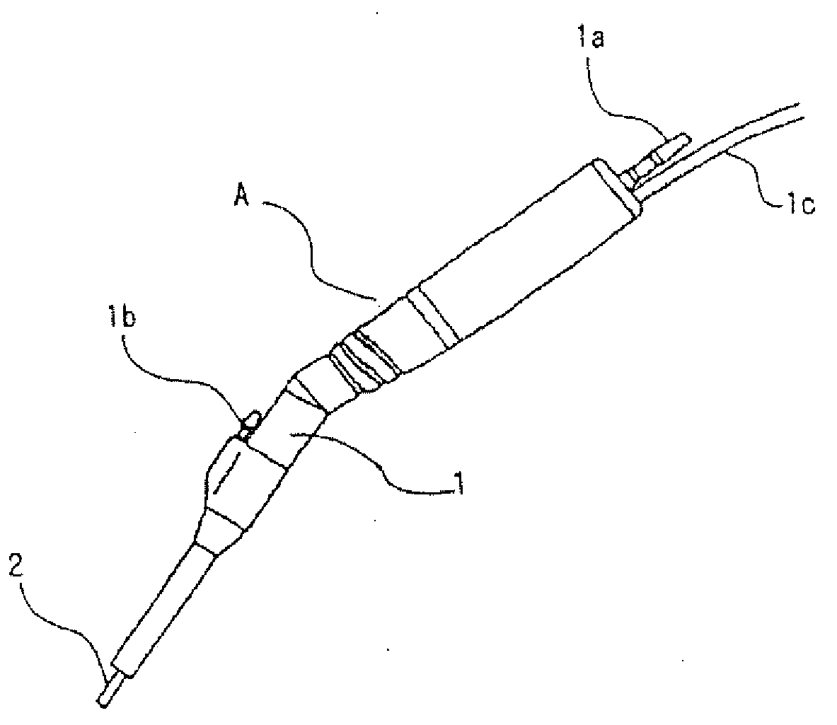
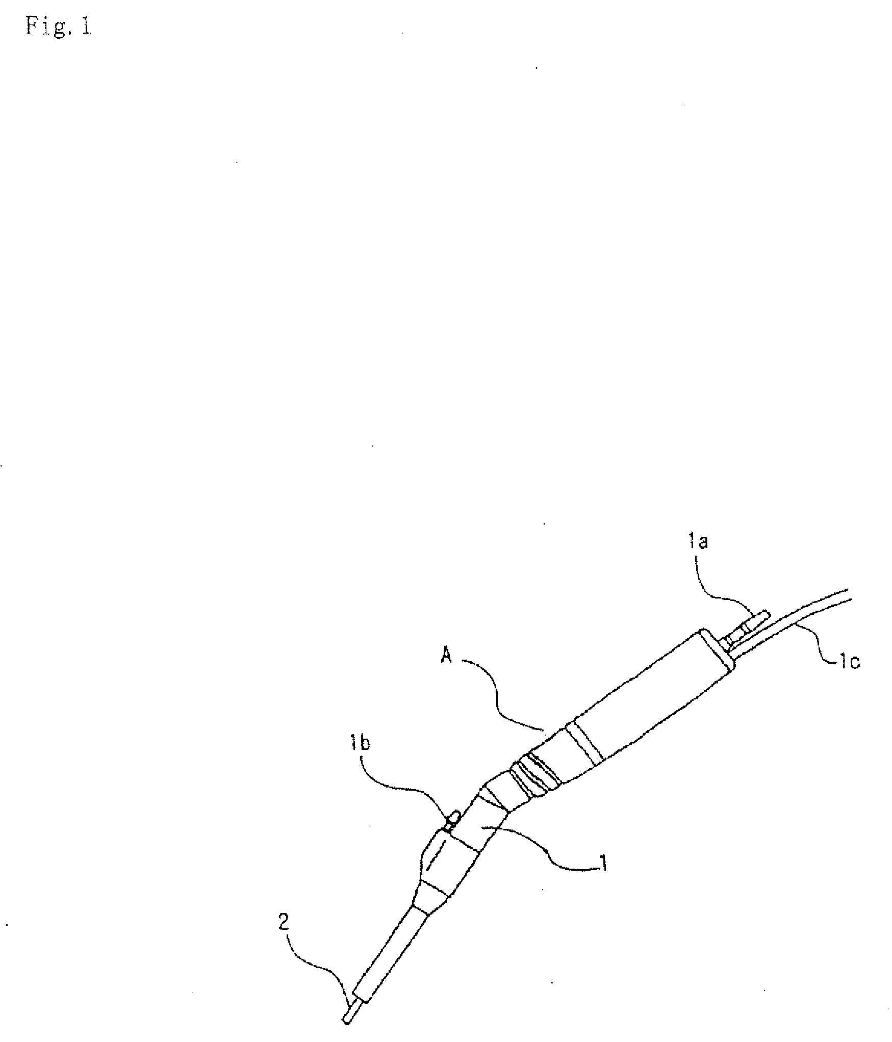
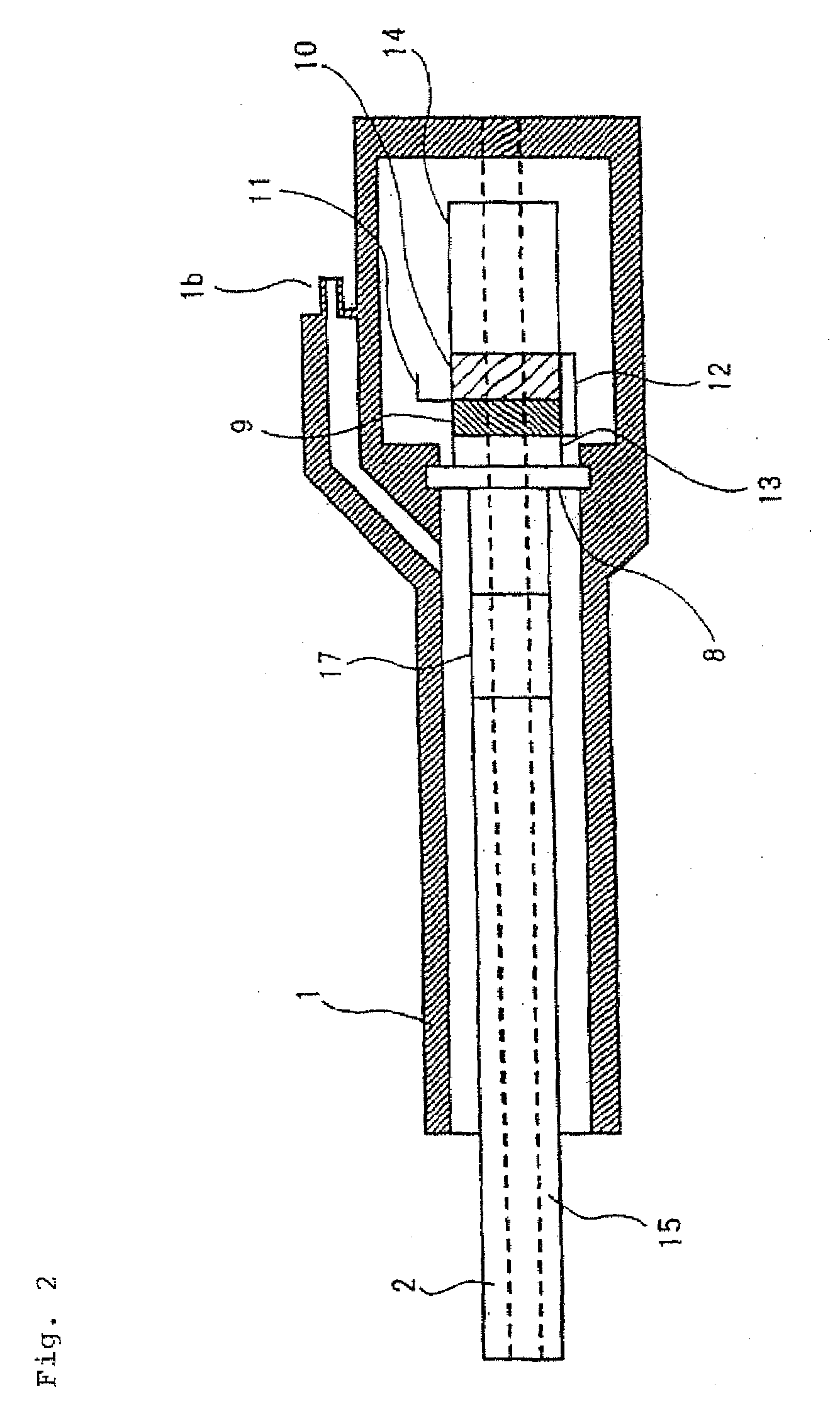
[0063]In the present embodiment, external cylinder 1 and horn 2 of the conventional handpiece for an ultrasonic surgical instrument shown in FIGS. 12 and 1 are replaced with external cylinder 101 and horn 102, and a part of external cylinder 101 covering horn 102 except for these is quite similar to the conventional art shown in FIGS. 12 and 1. Then, in FIGS. 8A and 8B, only external cylinder 101 and horn 102 are shown, and description of the part of external cylinder 101 covering horn 102 except for these will be omitted.

[0064]FIGS. 8A and 8B are an outline view and a cross-section view of a tip portion of horn 102 protruding from external cylinder 101 and abutting against an affected area of the body.

[0065]Horn 102 o...


PUM


Abstract

The present invention aims to provide a handpiece and a horn for an ultrasonic surgical instrument in which better visual recognition of a tip portion of the horn can be given. The handpiece for an ultrasonic surgical instrument includes: a horn of which tip portion vibrates at an ultrasonic wave velocity; and an external cylinder for covering the horn except the tip portion. An external diameter of the tip portion of the horn is larger than an external diameter of a part covered by the external cylinder.

Description

[0001]This application is based upon and claims the benefit of priority from Japanese patent application No. 2006-308529, filed on Nov. 15, 2006, the disclosure of which is incorporated herein in its entirety by reference.BACKGROUND OF THE INVENTION [0002]1. Field of the Invention[0003]The present invention relates to a handpiece and a horn of an ultrasonic surgical instrument using ultrasonic vibration.[0004]2. Description of the Related Art[0005]In medical treatment, conventionally, as one of various surgical instruments in the surgical field, many ultrasonic handpieces have been used. FIG. 1 shows such ultrasonic handpiece A.[0006]In FIG. 1, external cylinder 1 contains an ultrasonic vibration structure including a vibrator of, for example, a magneto-striction type and an electrostriction type, and which outputs ultrasound having a predetermined frequency. Horn 2 fits in an opening in one end portion of the external cylinder by insertion, and cuts hard tissues such as bone with t...

Claims


Application Information

Patent Timeline
IPC IPC(8): A61B17/32
CPCA61B17/320068A61B2017/320084A61B2017/320076A61B2017/320072A61B2017/320078A61B2017/320069A61B2017/32007A61B2017/320073
Inventor OTA, HIDEFUMISHIBATA, TOMOHIROSATO, YUICHIRO
Owner STRYKER CORP
Why Eureka
Try Eureka