Flexible electro-active lens

a flexible, electro-active technology, applied in the direction of instruments, prostheses, spectales/goggles, etc., can solve the problem of adding some thickness to the contact lens

Active Publication Date: 2008-08-28
E VISION SMART OPTICS INC
View PDF19 Cites 367 Cited by
  • Summary
  • Abstract
  • Description
  • Claims
  • Application Information

AI Technical Summary

Problems solved by technology

However, the electro-active element is rigid and therefore may add some thickness to the contact lens.

Method used


Image

  • Flexible electro-active lens
  • Flexible electro-active lens
  • Flexible electro-active lens

Examples


Embodiment Construction

[0019]The following preferred embodiments as exemplified by the drawings is illustrative of the invention and is not intended to limit the invention as encompassed by the claims of this application.

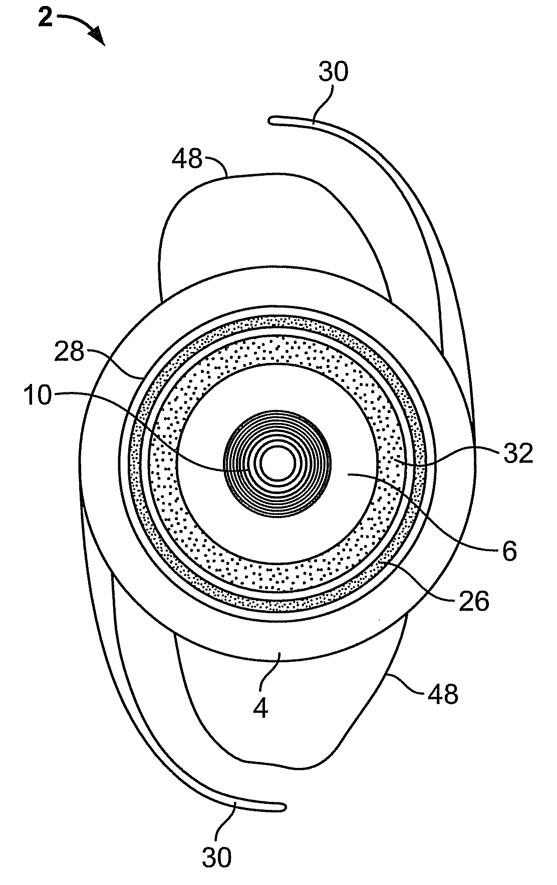
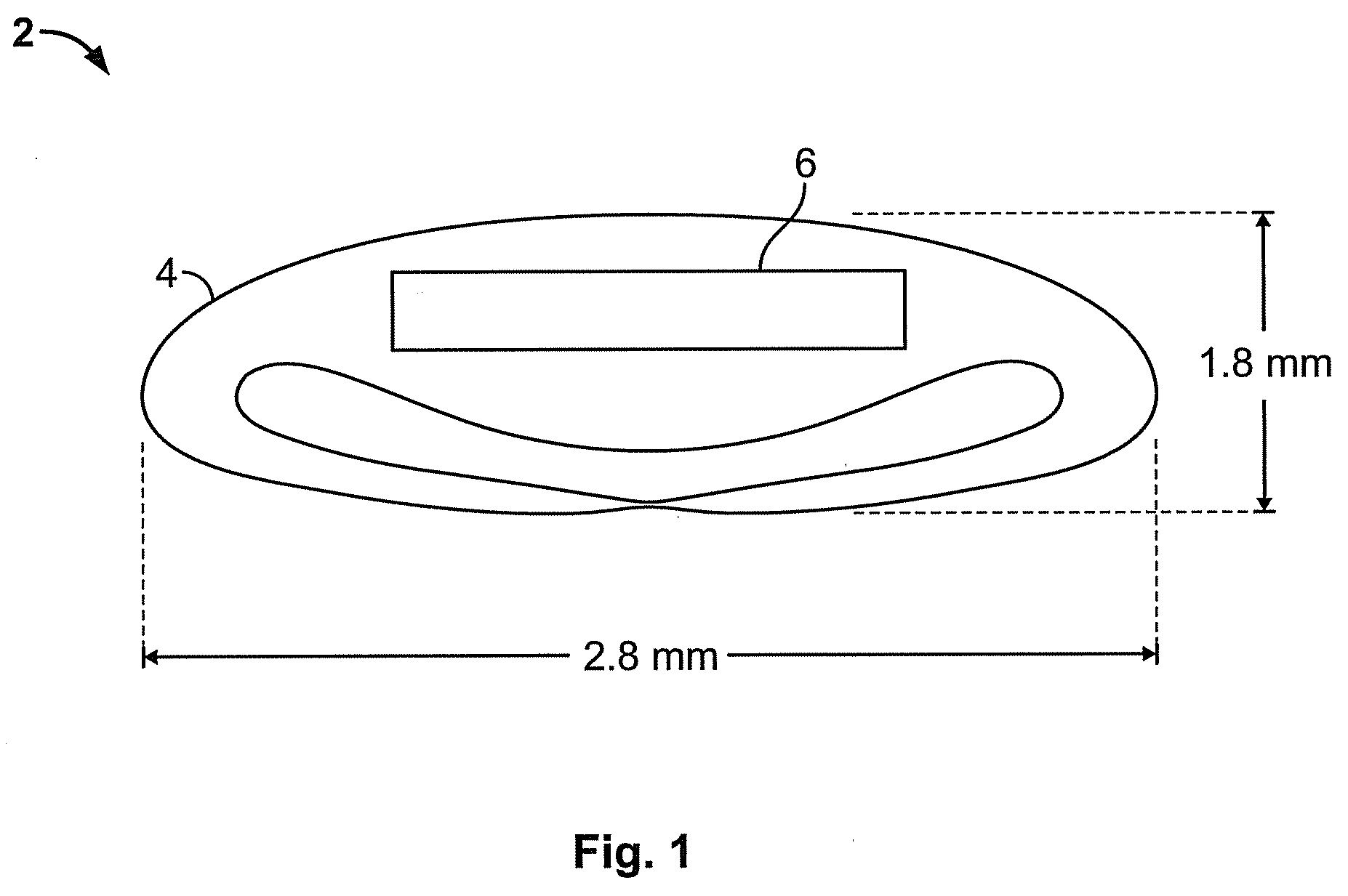
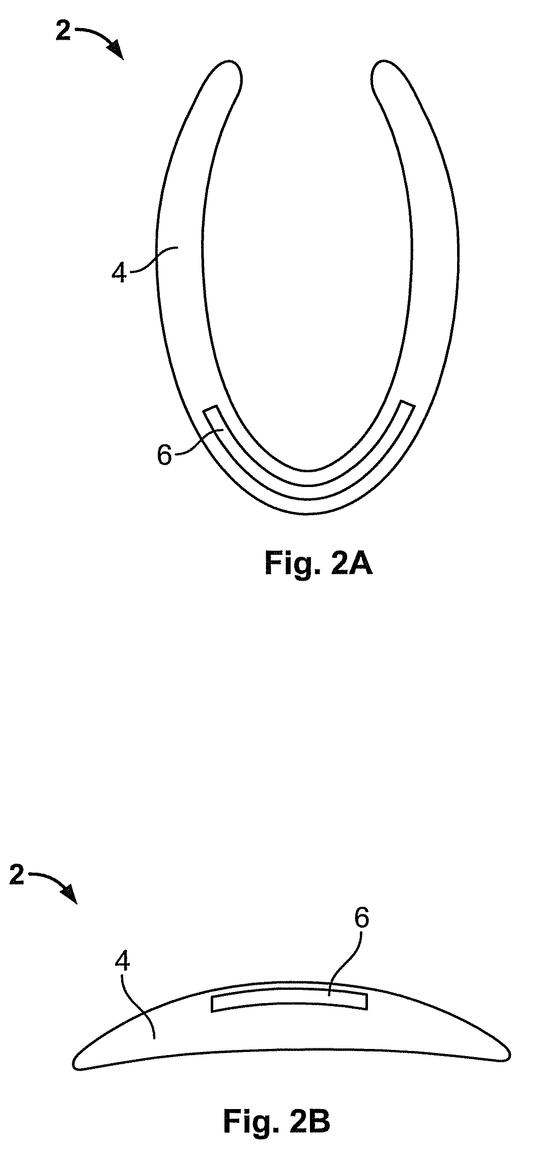
[0020]A flexible electro-active lens 2 is illustrated in FIG. 1, FIG. 2A, FIG. 2B, FIG. 3A, FIG. 3B, FIG. 4A, FIG. 4B, FIG. 5A, FIG. 5B, FIG. 5C, FIG. 5D, FIG. 7A, and FIG. 7B according to different embodiments of the present invention. Although the electro-active lens is described, embodiments of the invention may be used as other lenses including, for example, intraocular lenses, spectacle lenses, contact lenses, corneal onlays, corneal inlays, and inter-ocular lenses.

[0021]The electro-active element (e.g., described in reference to FIG. 1, FIG. 2A, FIG. 2B, FIG. 4A, FIG. 4B, FIG. 5A, FIG. 5B, FIG. 5C, FIG. 5D, FIG. 7A, and FIG. 7B), the liquid crystal layer (e.g., described in reference to FIG. 4A and FIG. 4B), and a pixilated element may all be used to describe materials having optica...


PUM

PropertyMeasurementUnit
sizeaaaaaaaaaa
temperatureaaaaaaaaaa

Abstract

A lens including a flexible refractive optic having a fixed refractive index, an electro-active element embedded within the flexible refractive optic, wherein the electro-active element has an alterable refractive index, and a controller electrically connected to the electro-active element wherein when power is applied thereto the refractive index of the electro-active element is altered.

Description

RELATED APPLICATION DATA[0001]The present invention claims priority from U.S. Provisional Application No. 60 / 881,514 filed, Jan. 22, 2007, titled, “Advanced Dynamic Electro-Active Intra-Ocular Lens”; and is related to U.S. Publication No. U.S. 2006 / 0095128-A1, Published May 4, 2006; U.S. Provisional Application No. 60 / 636,490, filed Dec. 17, 2004; U.S. Provisional Application No. 60 / 623,947, filed Nov. 2, 2004; U.S. Provisional Application No. 60 / 659,431, filed Mar. 9, 2005; U.S. Provisional Application No. 60 / 669,403, filed Apr. 8, 2005; and U.S. Provisional Application No. 60 / 960,607, filed Oct. 5, 2007, all of which are incorporated herein by reference in their entirety.BACKGROUND OF THE INVENTION[0002]Intraocular lenses (IOLs) may be used within the surface of an eye for restoring vision function, for example, via implant for patients of cataract surgery. IOLs include monofocal lenses, which provide a single focus or single optical power, multifocal lenses, which provide multipl...

Claims


Application Information

Patent Timeline
Patent Type & Authority Applications(United States)
IPC IPC(8): A61F2/16
CPCA61F2/1616A61N1/0543G02C2202/20G02C7/083G02C2202/18G02C7/04G02B1/043G02C7/049A61F2/145A61F2250/0001A61F2/1627C08L29/10C08L33/24C08L81/06G02C7/06A61F9/013
Inventor BLUM, RONALD D.HADDOCK, JOSHUA N.KOKONASKI, WILLIAMHUNKELER, JOHN
Owner E VISION SMART OPTICS INC
Why Eureka
Try Eureka