Intervertebral Implant Devices and Methods for Insertion Thereof

a technology of intervertebral implants and implants, which is applied in the field of intervertebral implant devices and methods for insertion thereof, can solve the problems of spinal nerve roots compression, pain or limited physical mobility of people, and reduced mobility of peopl

Active Publication Date: 2008-08-28
XTANT MEDICAL HLDG INC
View PDF102 Cites 150 Cited by
  • Summary
  • Abstract
  • Description
  • Claims
  • Application Information

AI Technical Summary

Benefits of technology

[0008]Thus, according to one aspect of the invention, an implant device is provided that is configured for implantation at multiple locations between adjacent vertebrae. In this manner, the implant device configuration provides several options with respect to implantation sites. The implant device comprises an implant body, a first portion of the implant body, and a second portion of the implant body. The second portion adjustably interconnected with the first portion such that the implant body has a compact orientation and an extended orientation. The adjustable interconnection also permits the implant body to be shifted from one orientation to the other orientation, enabling the implant body to be positioned in any one of areas between the spinous processes of the adjacent vertebrae, between laminar regions of the adjacent vertebrae, spanning an opening in the annulus between the adjacent vertebrae, or in the intervertebral space between the adjacent vertebrae.

Problems solved by technology

A variety of spinal conditions including, for example, trauma, deformity, disease, or other degenerative conditions, may result in a person experiencing pain or limited physical mobility.
This pain and reduced mobility is often attributed to the rupture or degeneration of the intervertebral discs resulting in compression of spinal nerve roots.
There are a number of limitations of existing interspinous implant devices, including the inability to accommodate the distinct anatomical structures of the spine, to minimize the subsidence and fracture potential, and to be inserted through minimally invasive surgical procedures.
Further, the success of existing methods often depends on the health of the annulus, which may be compromised during the surgical procedure or through the degenerative disc disease process.
The annulus may have surgical incisions, tears or be poorly nourished and weak such that it cannot adequately serve, by itself, to restrain an implant device, such as a nucleus replacement device, within the confines of the annulus.

Method used


Image

  • Intervertebral Implant Devices and Methods for Insertion Thereof
  • Intervertebral Implant Devices and Methods for Insertion Thereof
  • Intervertebral Implant Devices and Methods for Insertion Thereof

Examples


Embodiment Construction

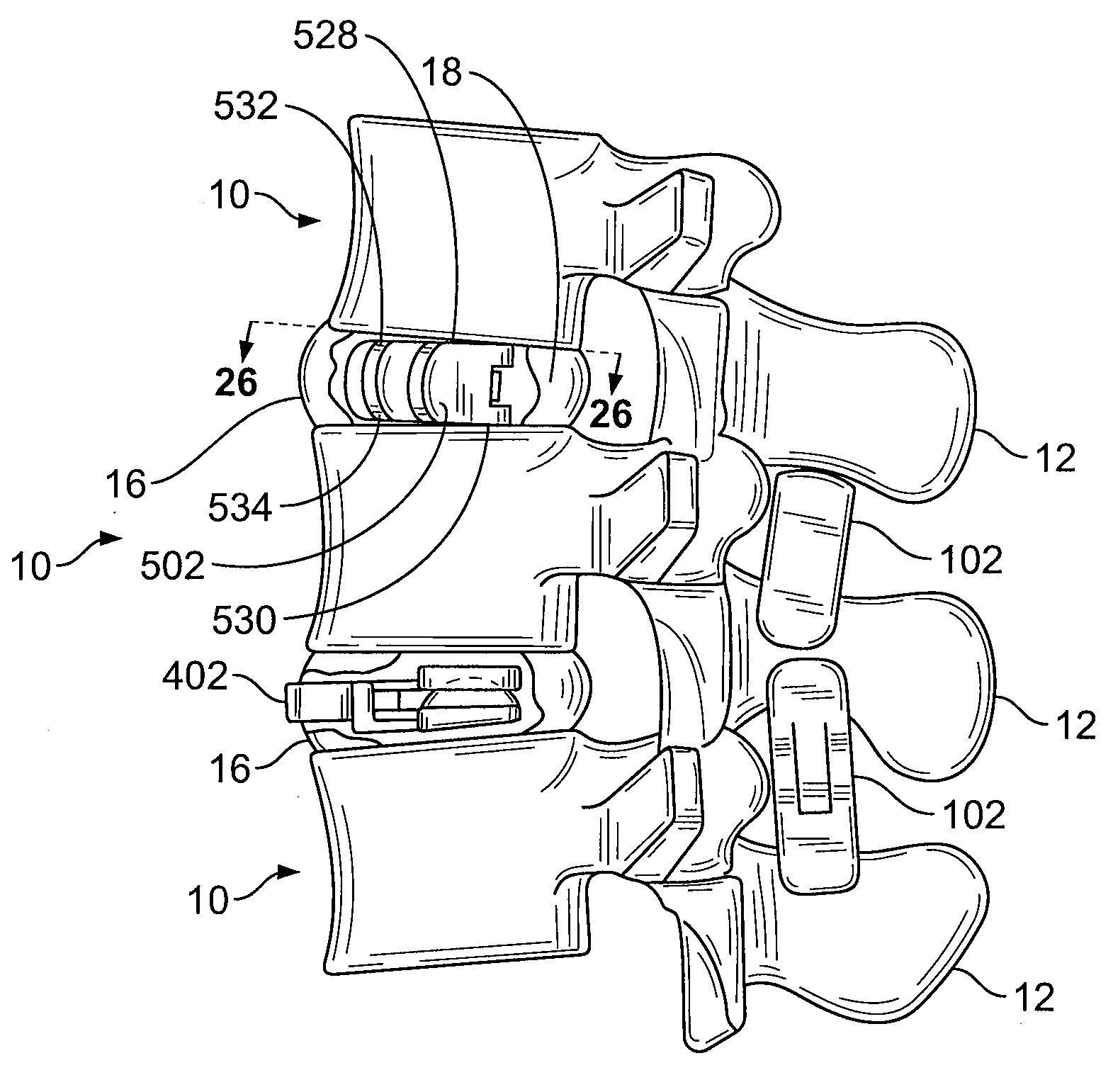
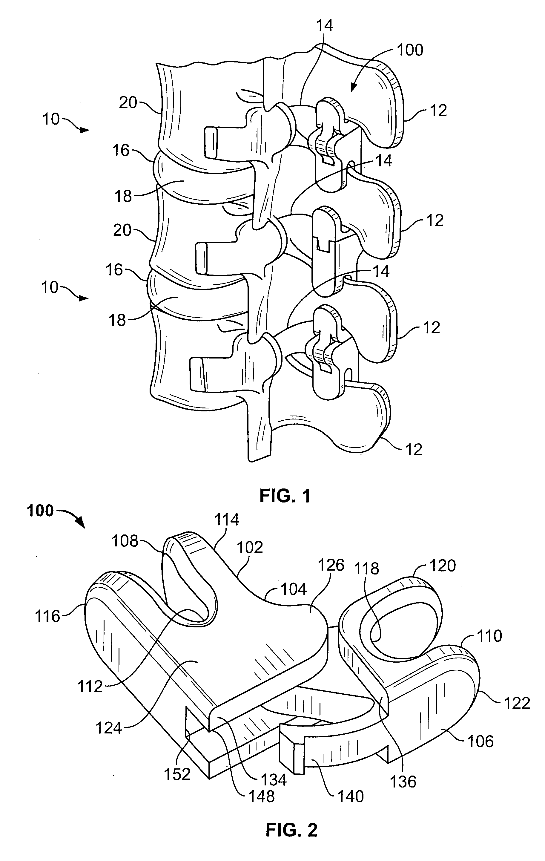
[0131]With reference to FIGS. 1-26, an implant device is shown configured in accordance with various aspects of the invention for being implanted at multiple different locations between adjacent vertebrae 10, including, for example, between the spinous processes 12, between laminar regions 14, in an opening in the annulus 16, and / or in the intervertebral space 18 between adjacent vertebral bodies 20.

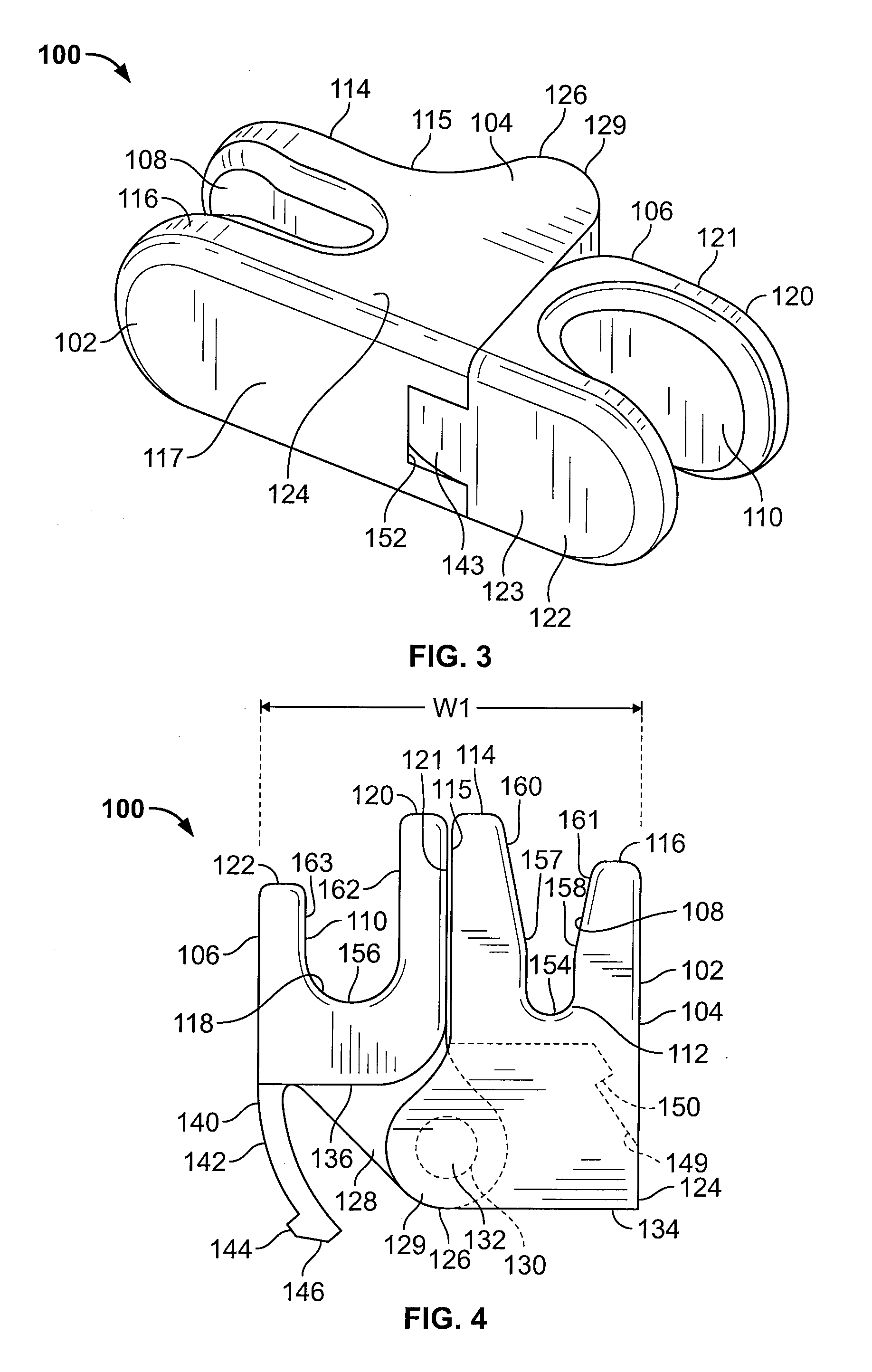
[0132]With reference to FIGS. 1-6, implant device 100 is shown in accordance with one aspect of the invention. Implant device 100 comprises an implant body 102 configured for being positioned between spinous processes 12 of adjacent vertebrae 10. The implant body 102 includes a first portion or member 104 and a second portion or member 106 adjustably interconnected such that the implant body 102 can be arranged in a compact orientation (as shown in FIG. 4, for example), an extended orientation (as shown in FIG. 6, for example), or an intermediate orientation (as shown in FIG. 5, for exam...


PUM


Abstract

An implant device is provided that is configured for implantation at multiple locations between adjacent vertebrae. The implant device comprises an implant body, a first portion of the implant body, and a second portion of the implant body adjustably interconnected with the first portion. The implant body has a compact orientation and an extended orientation to allow the implant body to be shifted from one orientation to the other orientation for being positioned in any one of areas between the spinous processes of the adjacent vertebrae, between laminar regions of the adjacent vertebrae, spanning an opening in the annulus between the adjacent vertebrae, and in the intervertebral space between the adjacent vertebrae.

Description

CROSS-REFERENCE OF RELATED APPLICATIONS[0001]This application claims the benefit of Provisional Application Ser. No. 60 / 888,509 filed on Feb. 6, 2007 and Provisional Application Ser. No. 60 / 981,824 filed on Oct. 23, 2007, the disclosure of which is hereby incorporated in its entirety by reference.FIELD OF THE INVENTION[0002]The invention relates to implant devices for implantation between adjacent vertebrae and, in particular, to implant devices positionable between spinous processes of adjacent vertebrae, between laminar regions of adjacent vertebrae, spanning an opening in the annulus between adjacent vertebral bodies, and / or in the intervertebral space between adjacent vertebral bodies, and to methods for the implantation of such devices.BACKGROUND OF THE INVENTION[0003]A variety of spinal conditions including, for example, trauma, deformity, disease, or other degenerative conditions, may result in a person experiencing pain or limited physical mobility. This pain and reduced mob...

Claims


Application Information

Patent Timeline
Patent Type & Authority Applications(United States)
IPC IPC(8): A61F2/44
CPCA61B17/70A61B17/7068A61B17/7071A61B2017/0256A61F2/442A61F2002/30131A61F2002/30166A61F2002/30471A61F2002/305A61F2002/30522A61F2002/30563A61F2002/30565A61F2002/30579A61F2002/30604A61F2002/30616A61F2002/30685A61F2002/4435A61F2002/444A61F2002/4622A61F2220/0025A61F2220/0091A61F2230/0013A61F2230/0028A61B17/7065
Inventor KILPELA, THOMAS S.JANOWSKI, BRIAN P.TRUDEAU, JEFFREY L.PIETILA, RUSSELL M.JACKSON, MICHAEL R.SULLIVAN, JOHN
Owner XTANT MEDICAL HLDG INC
Why Eureka
Try Eureka