Expandable subtabar implant

a subtabar implant and expandable technology, applied in the field of expandable subtabar implants, can solve the problems of insufficiently solving problems, anatomical misalignment, flattening of the inside arch of the foot, etc., and achieve the effect of blocking excessive motion

Inactive Publication Date: 2008-08-28
LOWE JOHN PATRICK TRUSTEE CHAPTER 7 CASE NO 09 51026 C IN THE UNITED STATES BANKRUPTCY COURT FOR THE WESTERN DISTRICT OF TEXAS SAN ANTONIO DIV
View PDF11 Cites 25 Cited by
  • Summary
  • Abstract
  • Description
  • Claims
  • Application Information

AI Technical Summary

Benefits of technology

[0018]In fulfillment of the above and further objectives, the present invention provides an improved expandable subtalar implant device suitable for addressing a flatfoot condition. The device is a sinus tarsi implant that serves to block excessive motion between the talus and calcaneus bones in the foot while still permitting normal motion and alignment. The device comprises a generally cylindrical metal structure having a first cylindrical (proximal) expandable end and a second slightly tapered (distal) adjustment end. A first outer component of the implant forms the external cylindrical end sections mentioned above and a second inner component comprises a movable (rotatable) ...

Problems solved by technology

The result of this abnormality is that the inside arch of the foot becomes flattened, generally as a result of the calcaneus or heel bone turning outward.
This abnormal motion of the ankle bone (talus) with respect to the calcaneus can eventually cause anatomical misalignment and therefore requires some correction.
Various structural configurations have been offered for such an implant, although none have been found fully satisfactory in solving the problems associated with placing the implant, maintaining it in place, and of course, having the implant function properly during normal motion of the foot.
Many designs previously offered have unfortunately focused almost entirely on the ease with which the implant is placed and its proper alignment within the sinus tarsi.
A second issue with subtalar implants is the ability to maintain the implant in place and to prevent misalig...

Method used


Image

  • Expandable subtabar implant
  • Expandable subtabar implant
  • Expandable subtabar implant

Examples


Embodiment Construction

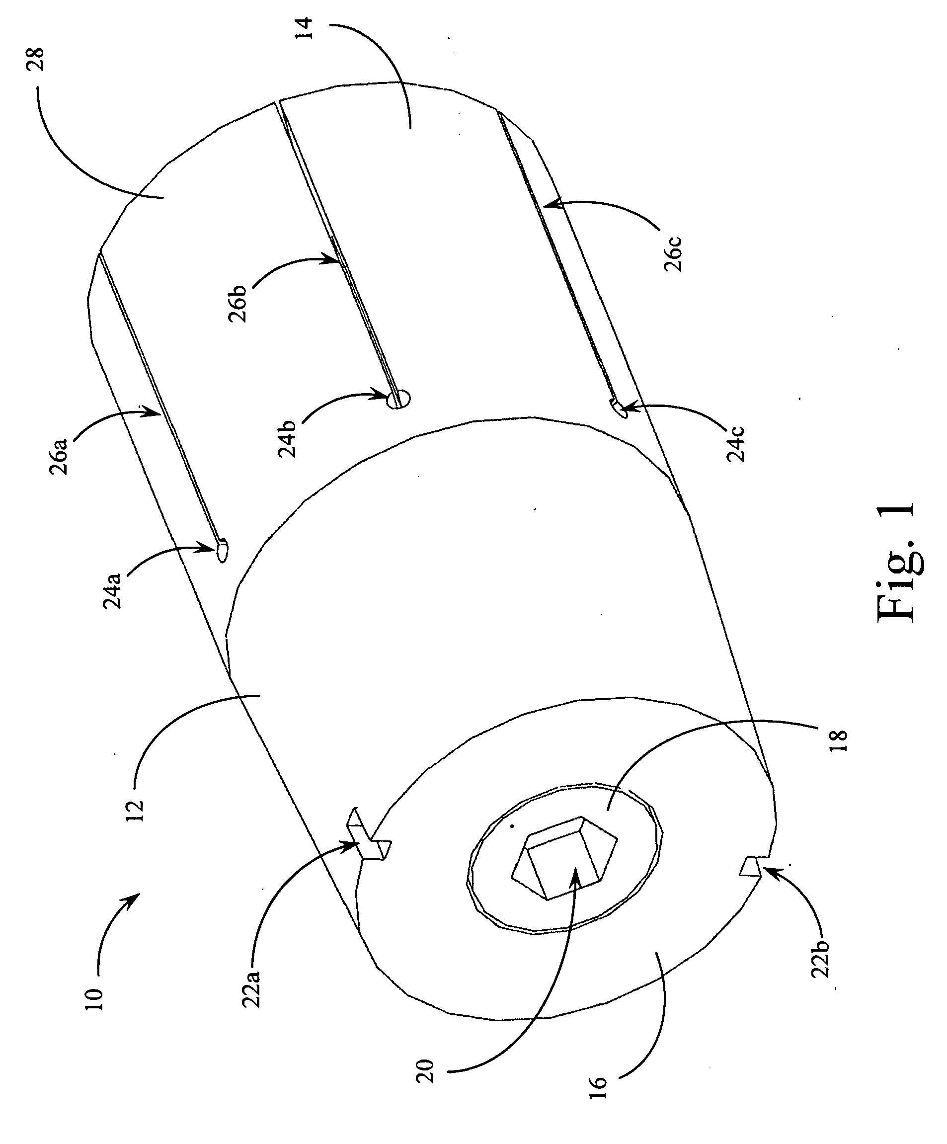
[0025]Reference is made first to FIG. 1 which discloses the overall structure of the subtalar implant device of the present invention. In FIG. 1, subtalar implant device 10 is seen in a perspective view which exhibits each of the components of the device as well as its external structural features. The tapered head section 12 of implant device 10 is generally cylindrical in structure and tapers from an approximate midpoint on the implant to what ends up being the exposed distal face 16 of the implant device. The balance of subtalar implant device 10 comprises the expansion cylinder section 14 of the device described in more detail below.

[0026]Hex screw 18 is centrally positioned within tapered head section 12 of the implant device, coaxially with the cylindrical structure of the implant device 10. As described in more detail below, hex screw 18 may, by way of engagement of a tool with internal hex socket 20, be threaded into, or threaded out from, engagement with tapered head sectio...


PUM


Abstract

An expandable subtalar implant device suitable for addressing a flatfoot condition. The device is a sinus tarsi implant that blocks excessive motion between the talus and calcaneus bones in the foot while permitting normal motion and alignment. The device comprises a generally cylindrical metal structure having a first proximal expandable end and a second distal adjustment end. A first component of the implant forms each of the cylindrical end sections and a second component comprises a movable internal rod that serves to progressively expand the outer cylinder of the implant. The internal rod is externally threaded and mates with internal threading on the cylindrical outer component. Progressive turning of the internal rod engages a number of radially arranged inclined surfaces that form the interior walls of the cylindrical shell component. Progressive engagement of the rod with these inclined surfaces forces the end of the cylindrical shell component outward; expanding the overall diameter of the implant once it has been positioned within the sinus tarsi.

Description

BACKGROUND OF THE INVENTION[0001]1. Field of the Invention[0002]The present invention relates generally to medical implant devices, especially those associated with modifying skeletal structure and motion. The present invention relates more specifically to an implant device for the correction of skeletal alignment deformities in the feet.[0003]2. Description of the Related Art[0004]A skeletal deformity in humans commonly referred to as “flatfoot” is an excessive pronation of the foot caused by abnormal motion between two bones of the foot. The result of this abnormality is that the inside arch of the foot becomes flattened, generally as a result of the calcaneus or heel bone turning outward. This abnormal motion of the ankle bone (talus) with respect to the calcaneus can eventually cause anatomical misalignment and therefore requires some correction.[0005]It is also known that in the above described motion between the talus and calcaneus, a naturally occurring opening (sinus) formed...

Claims


Application Information

Patent Timeline
IPC IPC(8): A61F2/42
CPCA61B17/562A61F2002/4223A61F2/4202A61B17/68
Inventor GRASER, ROBERT
Owner LOWE JOHN PATRICK TRUSTEE CHAPTER 7 CASE NO 09 51026 C IN THE UNITED STATES BANKRUPTCY COURT FOR THE WESTERN DISTRICT OF TEXAS SAN ANTONIO DIV
Why Eureka
Try Eureka