
Managing cache coherency in a data processing apparatus

Active Publication Date: 2008-08-28
ARM LTD
View PDF14 Cites 90 Cited by
  • Summary
  • Abstract
  • Description
  • Claims
  • Application Information

AI Technical Summary

Benefits of technology

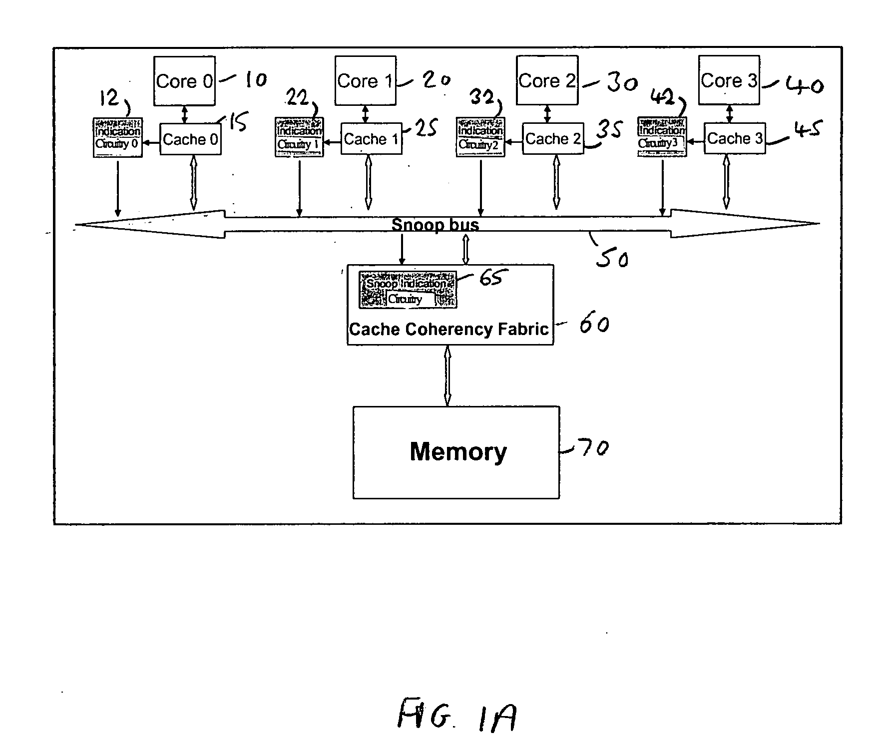
[0019]Since the content of the snoop indication circuitry provided in association with the cache coherency circuitry is derived from the segment filtering data already provided within the indication circuitry associated with each cache, this approach involves significantly less hardware cost than the known prior art techniques. Further, since the underlying segment filtering data from which the content of the snoop indication circuitry is derived provides information about the definite absence of data or potential presence of data on a segment-by-segment basis, the notifications issued to individual caches can provide more detailed information about the snoop operation to be performed than is possible in the known prior art techniques. For example, it is possible in embodiments of the present invention for such notification to not merely identify that the cache receiving that notification should perform a snoop operation, but also identifying to the cache the particular segments within the cache to be subjected to the snoop operation. This can yield significant further energy savings when compared with prior art techniques which would merely identify on a cache-by-cache basis whether a snoop operation should be performed within the cache.
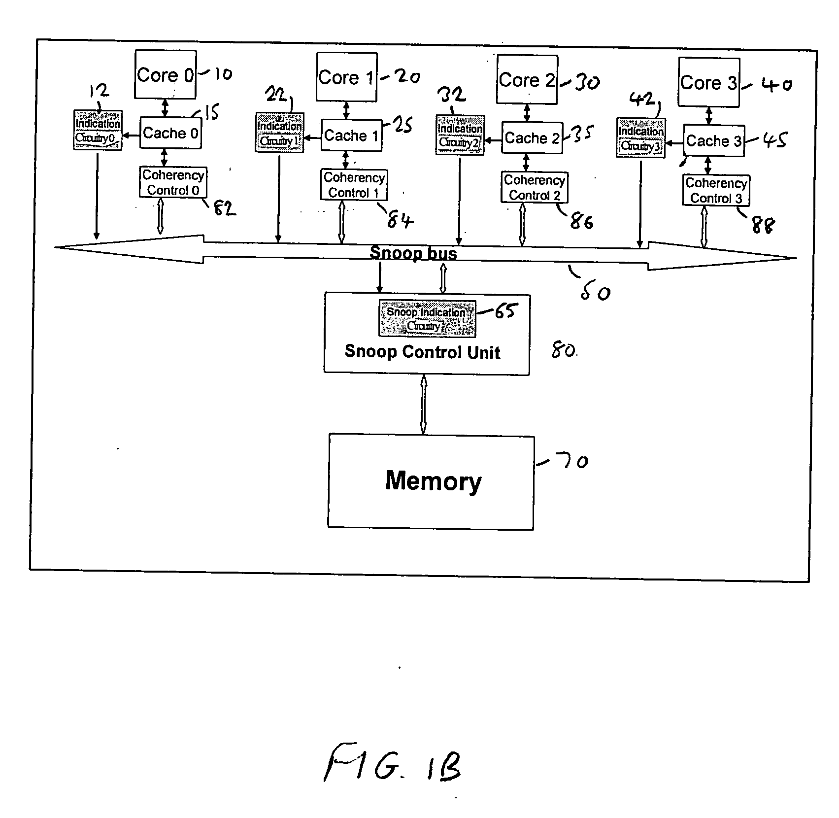
[0039]However, in an alternative embodiment, some of the above functionality of the cache coherency circuitry can be distributed so as to be provided more locally to each processing unit. In particular in one embodiment the cache coherency circuitry includes a snoop control unit and a plurality of coherency control units, each coherency control unit being associated with one of the processing units and its associated cache, and being arranged to determine which of the access requests issued by the associated processing unit should cause a coherency operation to be initiated by the snoop control unit. In such embodiments, a reduction in traffic received by the snoop control unit can be achieved, due to the filtering of access request performed by the coherency control units (the snoop control unit only being notified of those access requests that do require a coherency operation to be performed).

Problems solved by technology

Whilst this can improve speed of access to data, it complicates the issue of data coherency.
However, in a typical multi-processing system, much of the data will be shared amongst the processors, either because the data is generally classed as shared data, or because the multi-processing system allows for the migration of processes between processors, or indeed for a particular process to be run in parallel on multiple processors, with the result that even data that is specific to a particular process cannot be guaranteed to be exclusively used by a particular processor.
However, if in fact a copy of that cache line does not reside in the cache, nothing further is required, but some energy is consumed as a result of performing the snoop operation within the cache due to the lookup performed with respect to the tag entries of the cache.
Accordingly, it can be seen that the data processing apparatus consumes some considerable energy (also referred to a snoop energy) in performing snoop operations in order to find out whether a copy of a cache line exists in a cache or not.
Traditionally this is done for each cache associated with each processing unit, and if the snoop hit rate is very low (i.e. a large proportion of the caches subjected to the snoop operation do not locate a copy of the cache line in question), it is clear that significant snoop energy is wasted.
Whilst energy consumption in some multi-processing systems may not be a key concern, as use of multi-processing systems becomes more widespread, there are many modern day implementations (e.g. multi-core systems) where energy consumption is very important.
Two drawbacks of such an approach are that it can only reduce the volume of snoop operations resulting from read misses, and also it increases the latency of the load operation.
The main disadvantage of this technique is that when a PST entry is evicted, all cache blocks belonging to the page must be flushed from the cache.
In order to avoid this, the authors introduce an additional hardware mechanism, which complicates the design of the snoop filter hardware.
The disadvantage of this scheme is that every snoop request requires performance of a lookup in the local NSRT as well as the other NSRTs.
This increases energy consumption because of the NSRT tag lookups.

Method used


Image

  • Managing cache coherency in a data processing apparatus
  • Managing cache coherency in a data processing apparatus
  • Managing cache coherency in a data processing apparatus

Examples


Embodiment Construction

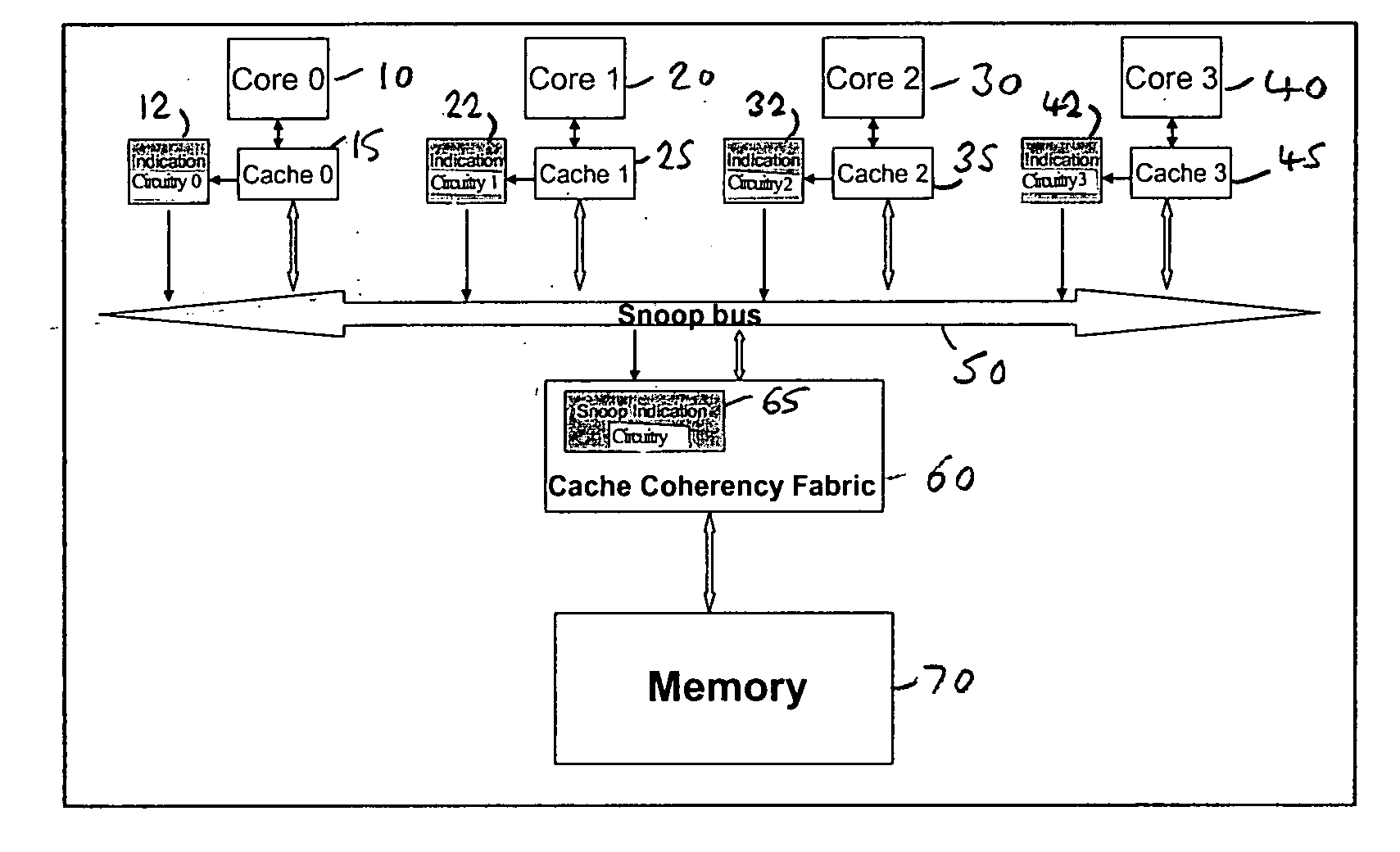
[0068]FIG. 1A is a block diagram of a data processing apparatus in accordance with one embodiment of the present invention. The data processing apparatus comprises a plurality of processor cores 10, 20, 30, 40, each provided with its own local cache circuitry 15, 25, 35, 45, respectively. Each cache circuitry may comprise a single cache or may comprise multiple caches. For example the cache circuitry 15 provided in association with core 10 may comprise a level one cache and optionally may also comprise a level two cache. Often, a level one cache will be split to provide a separate level one instruction cache and a separate level one data cache. For a level two cache, it is more often the case that a unified cache structure is provided for storing both instructions and data. For the purposes of the present application, the term “data” will be used to refer generally to both instructions to be executed by a core and data manipulated by the core when executing those instructions.

[0069]...


PUM


Abstract

A data processing apparatus and method are provided for managing cache coherency. The data processing apparatus comprises a plurality of processing units, each having a cache associated therewith, and each cache having indication circuitry containing segment filtering data. The indication circuitry is responsive to an address portion of an address specified by an access request from an associated processing unit to reference the segment filtering data in order to provide, for each of at least a subset of the segments of the associated cache, an indication as to whether the data is either definitely not stored in that segment or is potentially stored in that segment. Further, in accordance with the present invention, cache coherency circuitry is provided which employs a cache coherency protocol to ensure data accessed by each processing unit is up-to-date. The cache coherency circuitry has snoop indication circuitry associated therewith whose content is derived from the segment filtering data of each indication circuitry. For certain access requests, the cache coherency circuitry initiates a coherency operation during which the snoop indication circuitry is referenced to determine whether any of the caches require subjecting to a snoop operation. For each cache for which it is determined a snoop operation should be performed, the cache coherency circuitry is arranged to issue a notification to that cache identifying the snoop operation to be performed. By taking advantage of information already provided in association with each cache in order to form the content of the snoop indication circuitry, significant hardware cost savings are achieved when compared with prior art techniques. Further, through use of such an approach, it is possible in embodiments of the present invention to identify the snoop operation not only on a cache-by-cache basis, but also for a particular cache to identify which segments of that cache should be subjected to the snoop operation.

Description

BACKGROUND OF THE INVENTION[0001]1. Field of the Invention[0002]The present invention relates to techniques for managing cache coherency in a data processing apparatus.[0003]2. Description of the Prior Art[0004]It is known to provide multi-processing systems in which two or more processing units, for example processor cores, share access to shared memory. Such systems are typically used to gain higher performance by arranging the different processor cores to execute respective data processing operations in parallel. Known data processing systems which provide such multi-processing capabilities include IBM370 systems and SPARC multi-processing systems. These particular multi-processing systems are high performance systems where power efficiency and power consumption is of little concern and the main objective is maximum processing speed.[0005]To further improve speed of access to data within such a multi-processing system, it is known to provide each of the processing units with its ...

Claims


Application Information

Patent Timeline
IPC IPC(8): G06F13/00
CPCG06F12/0822Y02B60/1225G06F12/0831Y02D10/00
Inventor OZER, EMREBILES, STUART DAVIDFORD, SIMON ANDREW
Owner ARM LTD
Learn More