Eureka AIR delivers breakthrough ideas for toughest innovation challenges, trusted by R&D personnel around the world.

User interface system and method for inter-router protocol and transport configuration

a user interface and protocol technology, applied in the field of user interface systems, can solve the problems of laborious and time-consuming tasks, inefficient and repetitious tasks,

Active Publication Date: 2008-08-28
RPX CORP
View PDF6 Cites 10 Cited by
  • Summary
  • Abstract
  • Description
  • Claims
  • Application Information

AI Technical Summary

Problems solved by technology

Such a task can be laborious and time consuming, and usually is inefficient and repetitious.

Method used


Image

  • User interface system and method for inter-router protocol and transport configuration
  • User interface system and method for inter-router protocol and transport configuration
  • User interface system and method for inter-router protocol and transport configuration

Examples


Embodiment Construction

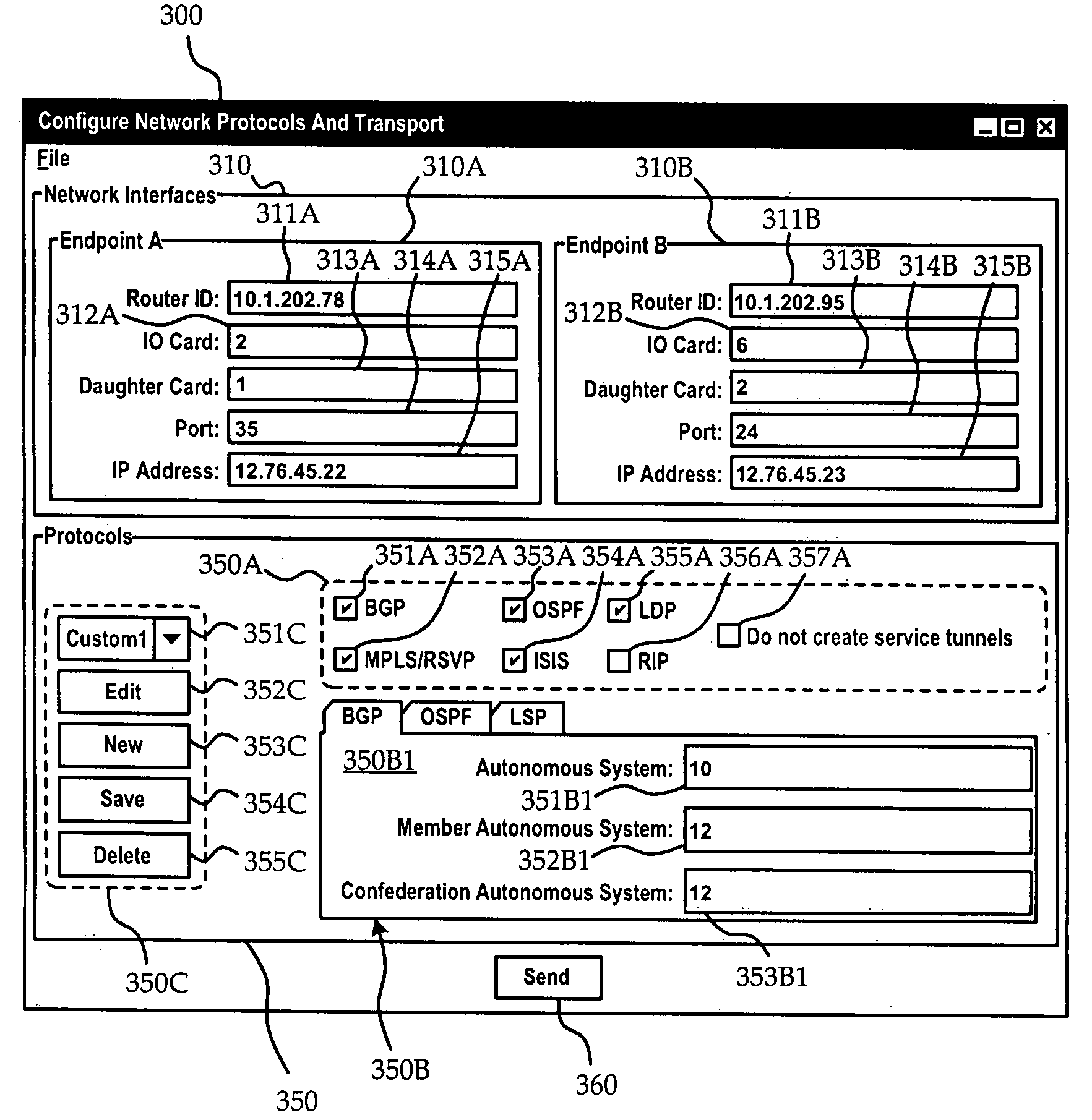
[0035]Referring now to FIGS. 3, 4, and 5 a GUI 300 according to the preferred embodiment will now be described. The GUI 300 primarily comprises a physical connection entry area 310 and a protocols entry area 350. As will be discussed below another embodiment provides a non-graphical user interface which, although non-graphical, provides the same number and type of entries as the GUI 300 depicted in FIGS. 3, 4, and 5.

[0036]As can be seen in each of FIGS. 3, 4, and 5, the single physical connection entry area 310 comprises endpoint entry areas 310A, 310B for each endpoint of the connection which is to be configured. Each endpoint entry area 310A, 310B comprises input fields for the endpoints of the connection. For example, the first endpoint entry area 310A for “Endpoint A” comprises a field to identify the routing instance 311A, and network interface parameters such as IO Card 312A, daughter card 313A, port 314A, and IP address 315A, which together identify the network interface of “...


PUM


Abstract

An interface system and method for creation and configuration of a connection between routers is provided. The interface comprises facility for entry of physical connection information, and entry of protocols selection and configuration information. Information for selection and configuring routing instances, network interfaces, and protocols for the connection is only requested from the user interface once before it is forwarded to an NMS to carry out the steps for actually setting-up the connection. Transport and protocol profiles for re-use with various physical connections are also provided.

Description

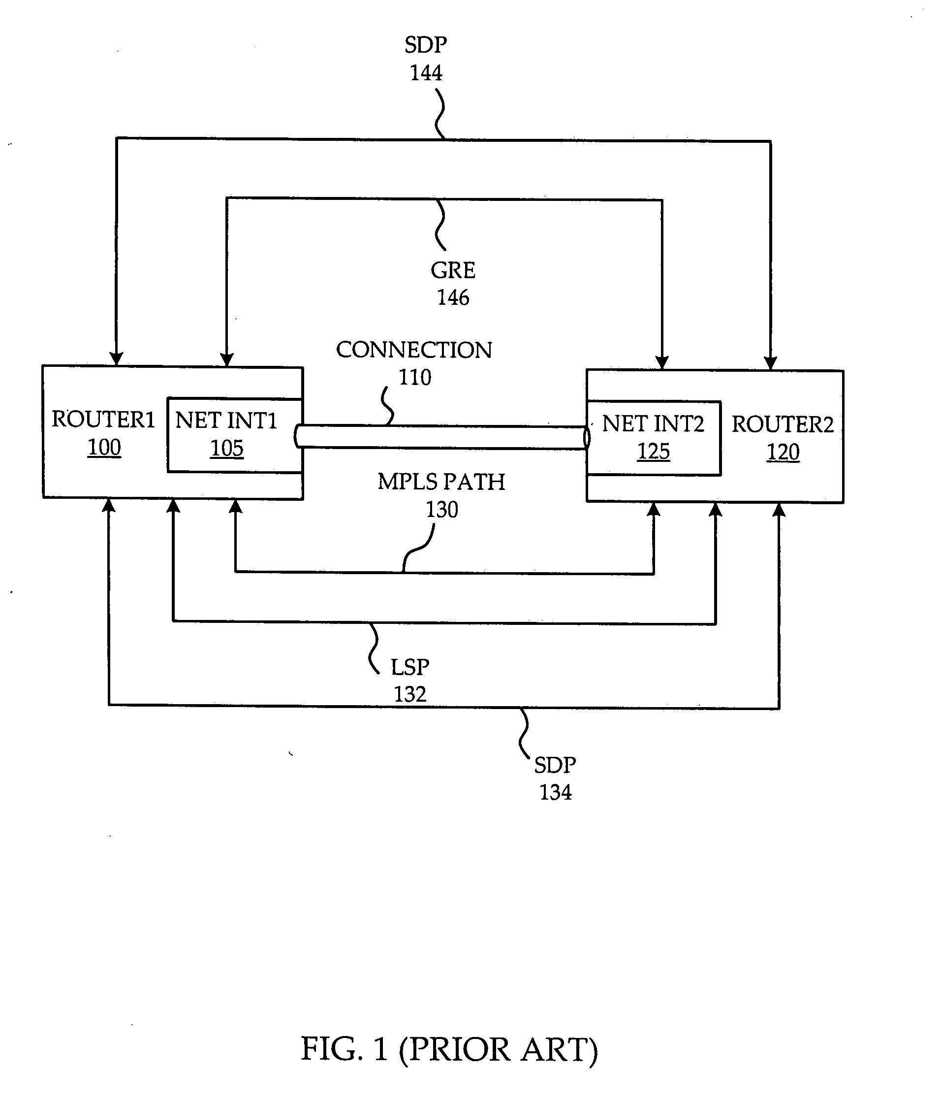
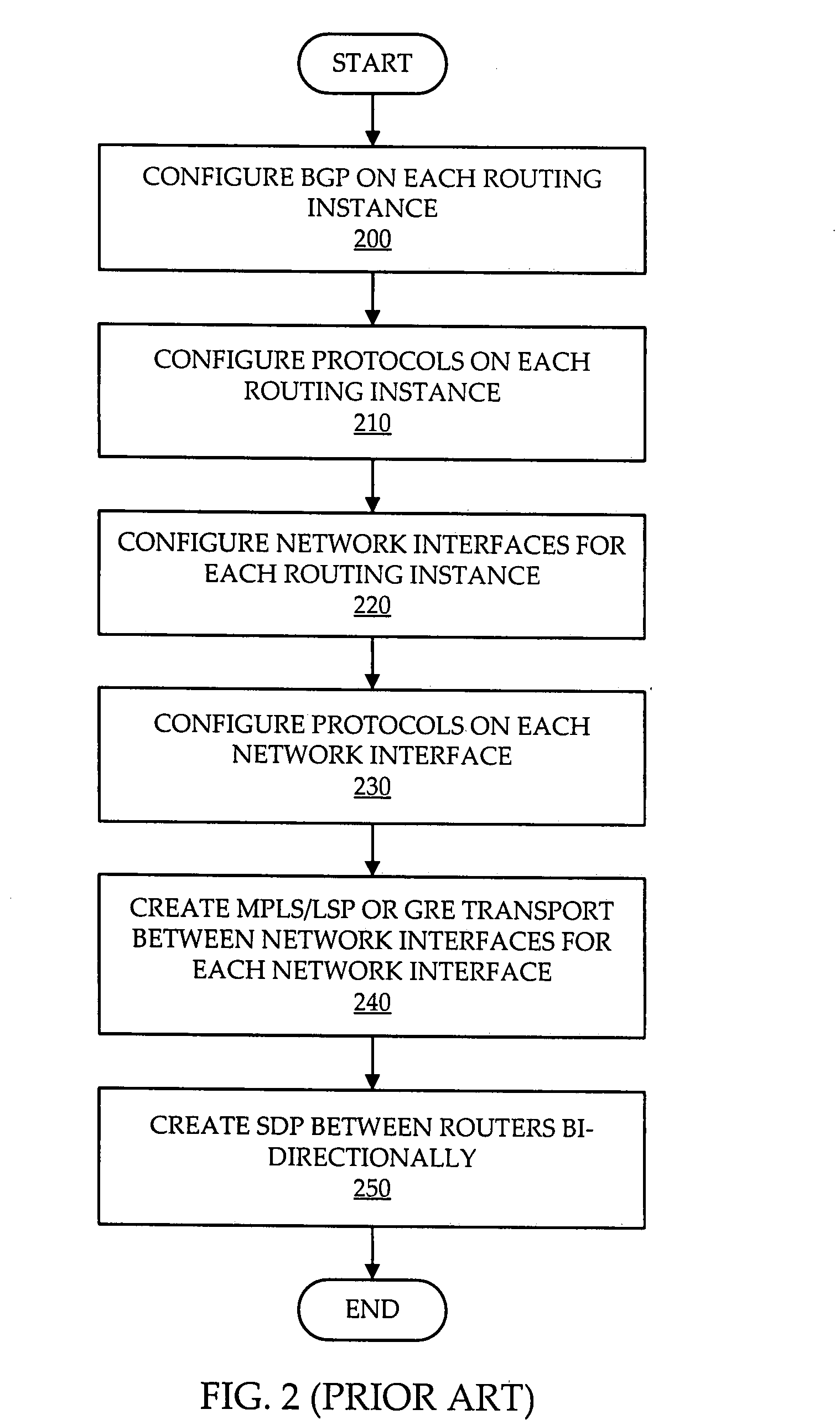
FIELD OF THE INVENTION[0001]The invention relates to user interface systems and more particularly to a user interface system of a Network Management System (NMS) for configuring inter-router connections.BACKGROUND OF THE INVENTION[0002]One of the common tasks performed by a network management infrastructure of a telecommunications network is the set-up and configuration of a connection between routers. Examples of two types of connections between routers are shown in FIG. 1.[0003]A first router 100 is connected with a second router 120 over a connection 110. The first router 100 has a first network interface 105 while the second router 120 has a second network interface 125. The connection 110 between the two network interfaces 105, 125 typically is one of two types of connection. The first type has GRE (generic routing protocol) transport 146 over which a service tunnel or SDP (service distribution path) 144 is maintained. The second has a service tunnel SDP 134 over an MPLS (multi...

Claims


Application Information

Patent Timeline
IPC IPC(8): G06F15/177
CPCG06F15/177H04L41/0806H04L41/22H04L45/52
Inventor PIRBHAI, RAHIMBRASSARD, JEFFREY
Owner RPX CORP
Why Eureka
Eureka Blog
Learn More