Cooling device with ringed fins

a cooling device and fin technology, applied in semiconductor devices, semiconductor/solid-state device details, lighting and heating apparatus, etc., can solve the problems of insufficient contact area between the condensing part of the heat pipe and the cooling structure, inability to completely develop the heat-transferring effect of individual heat pipes, and inability to transfer heat, etc., to achieve the effect of promoting the heat-transferring

Inactive Publication Date: 2008-09-04
COOLER MASTER CO LTD
View PDF10 Cites 15 Cited by
  • Summary
  • Abstract
  • Description
  • Claims
  • Application Information

AI Technical Summary

Benefits of technology

[0008]The invention is mainly to provide a cooling device with ringed fins, in which a heat pipe is applied as a heat-transferring element between a heat-conducting base and at least two fin sets. A condensing section applied as a thermal connection between the heat pipe and the fin sets is shown as a flat shape for the convenience of being positioned between two fin sets. Thereby, the contacting area of the condensing section of the heat pipe and each fin set may be enhanced significantly, and the heat transferring effect may be promoted markedly as well.

Problems solved by technology

However, although there is an excellent distribution and cooperation between the cooling device of heat pipe and the air flow supplied by the fan, it is impossible to develop the heat-transferring effect of individual heat pipe completely, because it ignores the fact that there is too little contacting area between the heat pipe and the fins.
On one hand, the cooling device of heat pipe poorly applies the heat-conducting tube as a heat-conducting media between the heat tube and the fins, such that the heat is unable to be transferred to the fins and the heat-transferring effect is influenced.
On the other hand, regarding the flat parts of the heat pipe to be thermally contacted with the heat-conducting tube, since there is only one flat face contacted with the heat-conducting tube, while another face is not contacted with any fin or cooling structure, there is insufficient contacting area between the condensing part of heat pipe and the cooling structure.
Therefore, the transferred heat can not be dissipated in time, causing the working fluid in the heat pipe unable to be restored to liquid phase, nor a heat exchange can be functioned successfully.

Method used


Image

  • Cooling device with ringed fins
  • Cooling device with ringed fins
  • Cooling device with ringed fins

Examples


Embodiment Construction

[0018]In cooperation with attached drawings, the technical contents and detailed description of the present invention are described thereinafter according to a number of preferable embodiments, being not used to limit its executing scope. Any equivalent variation and modification made according to appended claims is all covered by the claims claimed by the present invention.

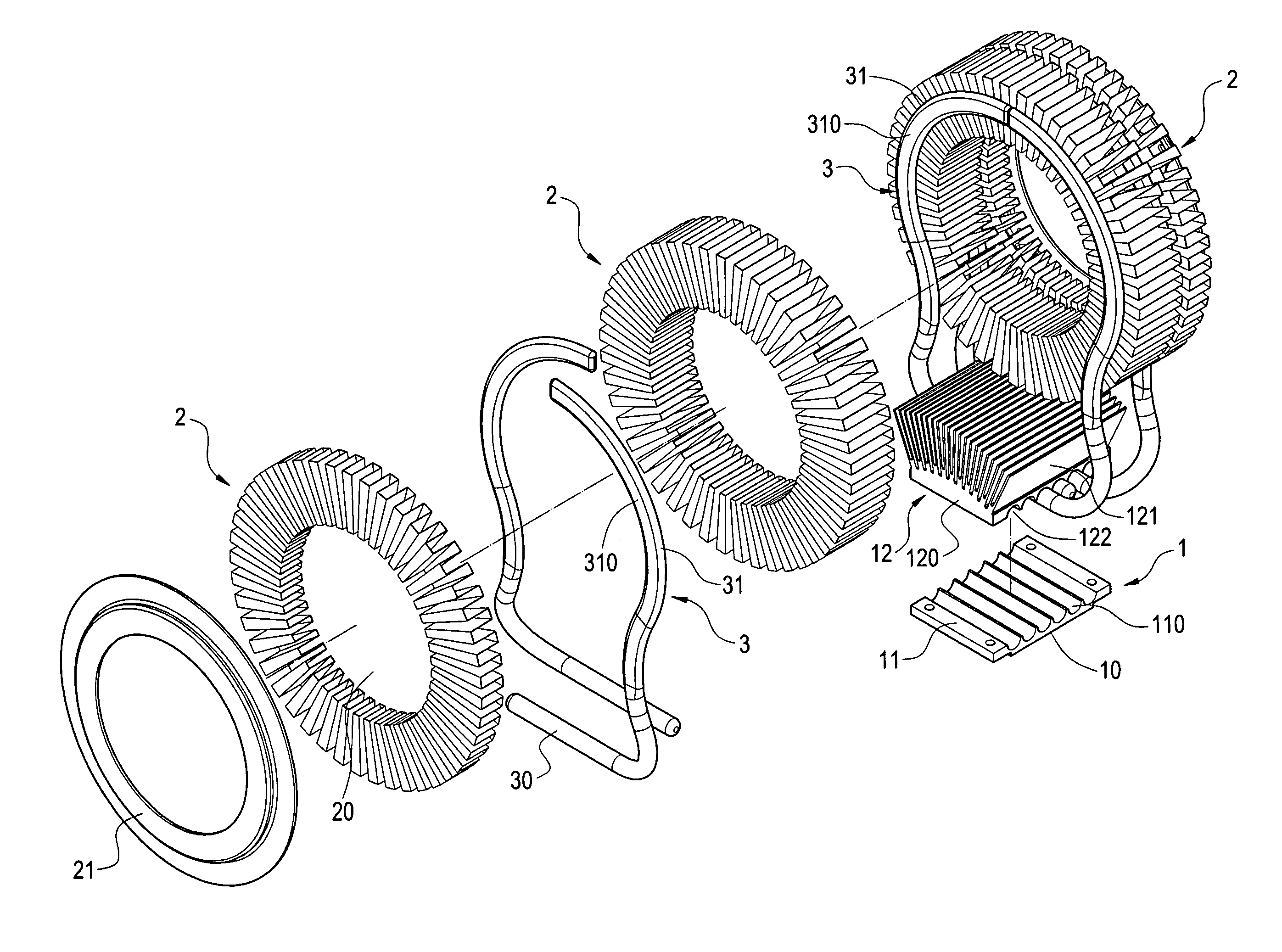
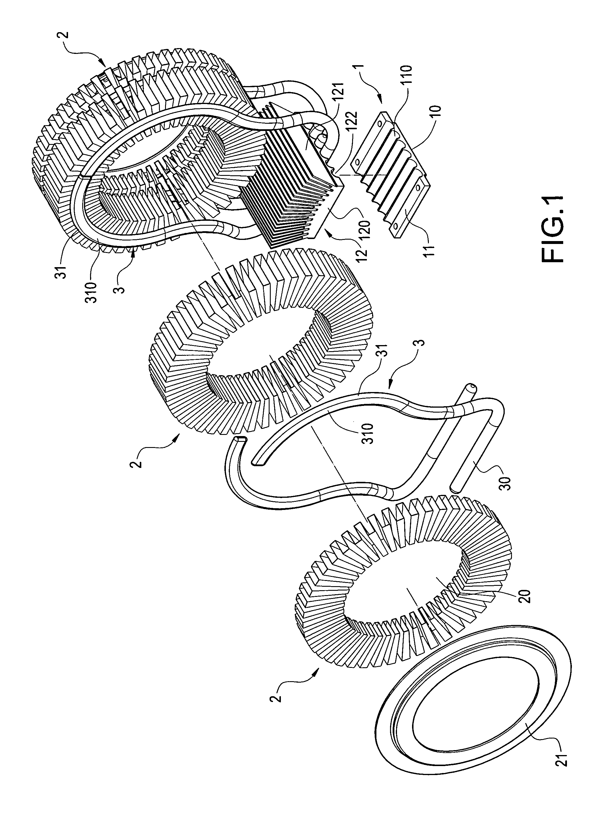
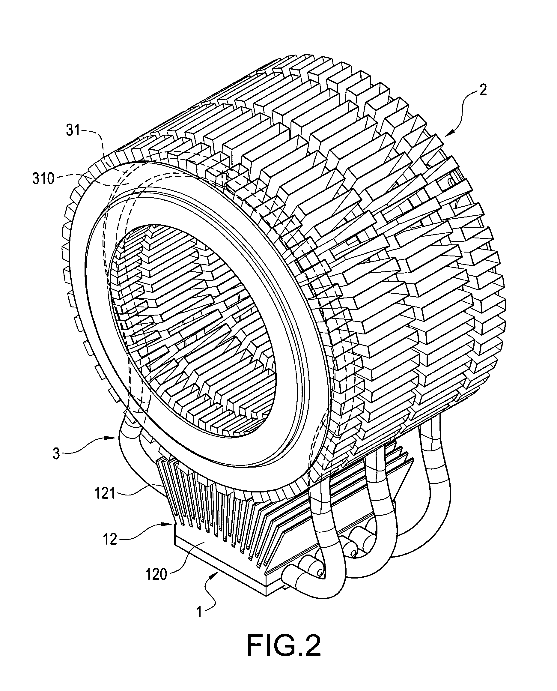
[0019]Please refer to FIG. 1 and FIG. 2, which respectively are a perspective explosive view and a perspective assembled view of the present invention. The invention is to provide a cooling device with ringed fins, which includes a heat-conducting base 1, at least two fin sets 2, and at least one heat pipe 3.

[0020]According to a preferable embodiment of the invention, the heat-conducting base 1 is made of materials with excellent heat conductivity, such as aluminum and copper. Its bottom face 10 is contacted closely with an electronic element 4, such as CPU, as shown in FIG. 4. A cooler 12 may be further arranged...


PUM


Abstract

A cooling device includes a heat-conducting base, two fin sets, and a heat pipe. The two fin sets are respectively constructed by a metallic stripe that is periodically folded and is arranged as a ring type. The heat pipe has a heated section that is thermally connected to the heat-conducting base, and a condensing section that is extended from the heat-conducting base is further formed as a flat shape, on which two oppositely flat faces are formed. The two flat faces of the condensing section of the heat pipe are respectively contacted closely with the two fin sets by being sandwiched therein. In such case, the contact area between the condensing section of heat pipe and the fin sets is enhanced, thus that the heat-conducting effect is promoted significantly.

Description

BACKGROUND OF THE INVENTION[0001]1. Field of the Invention[0002]The present invention generally relates to a cooler, and in particular, to a cooling device capable of solving the heating problem generated from an electronic element, such as CPU.[0003]2. Description of Prior Art[0004]In order to solve the cooling problem of electronic elements which generates a great amount of heat, such as the CPU of a computer, heat pipe has become an indispensable member associated with current cooling device. Additionally, in order to provide an excellent distribution and cooperation between the fins arranged on the cooling device and the air flow supplied by the fan, it can arrange at least one set of ringed fins to the heat-conducting seat formed in a tube shape as disclosed in the “Cooling Device of Heat Pipe” of Taiwan Patent Publication No. 575154.[0005]The cooling device of heat pipe includes a plate-typed base, a cylindrical heat-conducting tube with two sides opened, a plurality of heat p...

Claims


Application Information

Patent Timeline
Patent Type & Authority Applications(United States)
IPC IPC(8): F28F7/00
CPCH01L23/367H01L23/3672H01L23/427H01L2924/0002H01L2924/00
Inventor PENG, JI-PING
Owner COOLER MASTER CO LTD
Why Eureka
Try Eureka