Very high frequency line of sight winglet antenna

a line of sight and antenna technology, applied in the field of very high frequency line of sight antennas, can solve the problems of altering or degrading the aerodynamic characteristics of the aircraft, altering the cosmetic appearance of the aircraft, and current art aircraft antennas having co-location interference problems with other radios

Inactive Publication Date: 2008-09-04
L 3 COMM INTEGRATED SYST +1
View PDF18 Cites 10 Cited by
  • Summary
  • Abstract
  • Description
  • Claims
  • Application Information

AI Technical Summary

Benefits of technology

[0003]The methods and systems described herein provide a line of sight antenna supported in an aircraft wing with an upturned winglet or similar vertical member. As described below, the winglet antenna can be implemented using a cutaway aperture in a conductive winglet, a support structure configured to support the antenna in the aperture such that the antenna remains exposed to the line of sight transmissions, and a non-conductive covering for the aperture. In more detailed aspects, the antenna, as installed, does not substantially alter the appearance or aerodynamic characteristics of the aircraft. In another embodiment, the winglet antenna may be coupled to the outside of the non-conductive covering for the aperture. In addition, other features and variations could be implemented, if desired, and related methods can be utilized, as well.

Problems solved by technology

However, current art aircraft antennas have a co-location interference problem with other radios and their antennas that occur, mainly due to their location in the aircraft fuselage.
Further, the addition of current art antennas can alter the cosmetic appearance of the aircraft, or can alter or degrade the aerodynamic characteristics of the aircraft.
One current state of art High Frequency (HF) antenna installed in a right winglet of a GIII aircraft has a ⅝ inch diameter curved tube, but is not appropriate to service a Very High Frequency (VHF) radio.

Method used


Image

  • Very high frequency line of sight winglet antenna
  • Very high frequency line of sight winglet antenna
  • Very high frequency line of sight winglet antenna

Examples


Embodiment Construction

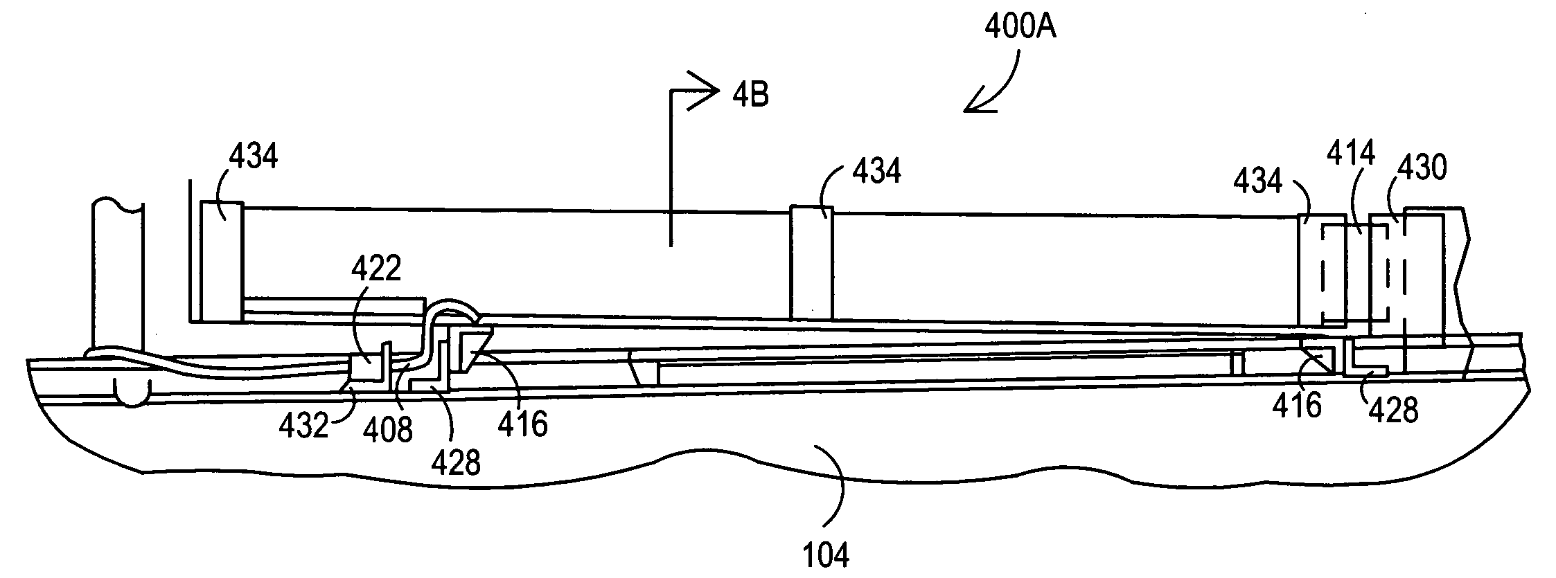
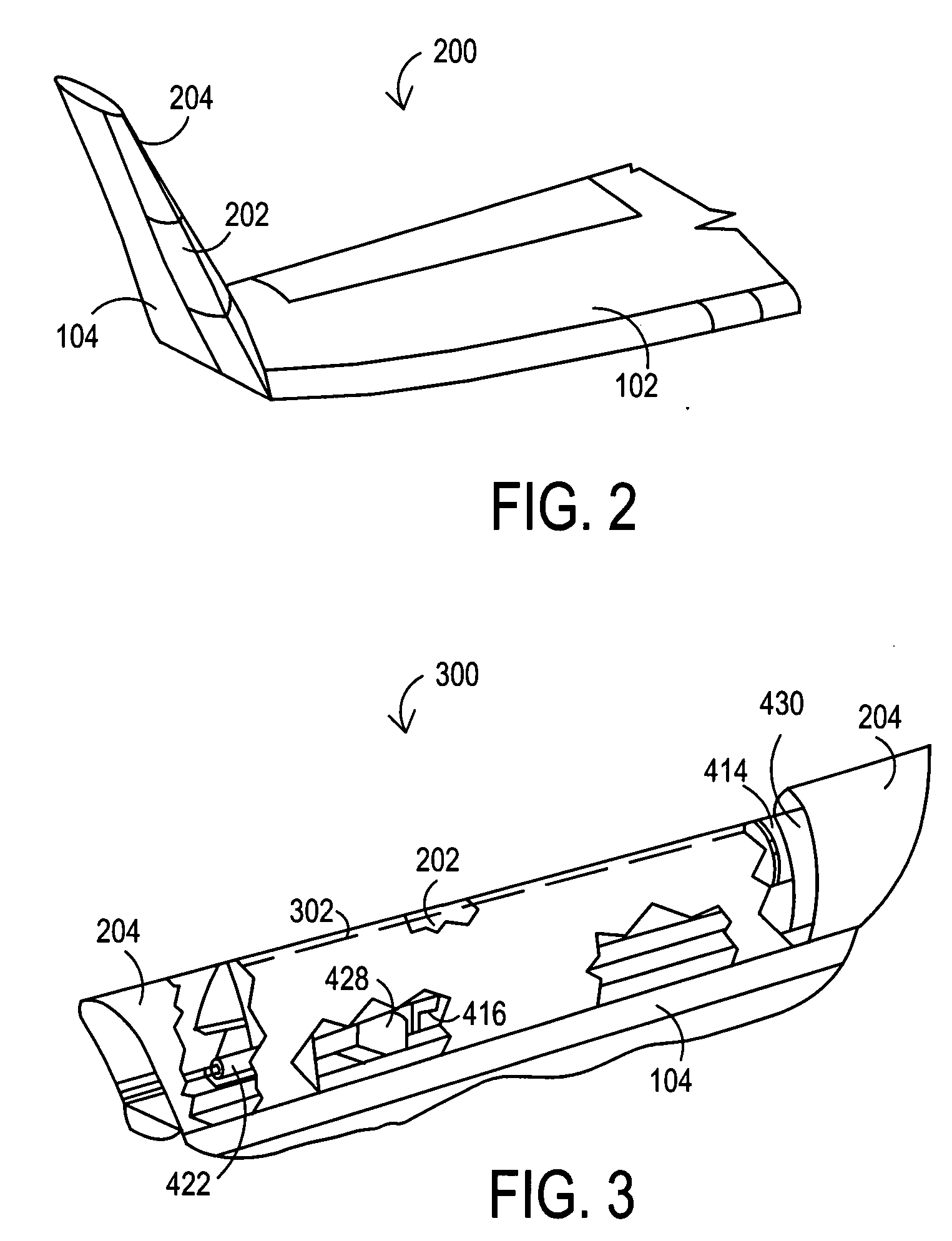
[0012]The systems and methods described herein provide a line of sight antenna supported by an aircraft wing with an upturned winglet or similar vertical member. In one implementation, an antenna is supported within a cutaway aperture in a conductive winglet or similar vertical member of an aircraft wing such that the antenna remains exposed to the line of sight transmissions. In addition, a non-conductive covering for the aperture can be used to improve the aerodynamic performance and / or cosmetic look of the aircraft wing. Further, the antenna could be coupled to the outside of the non-conductive covering if desired. The line of site winglet antenna will now be more fully described with respect to the drawings.

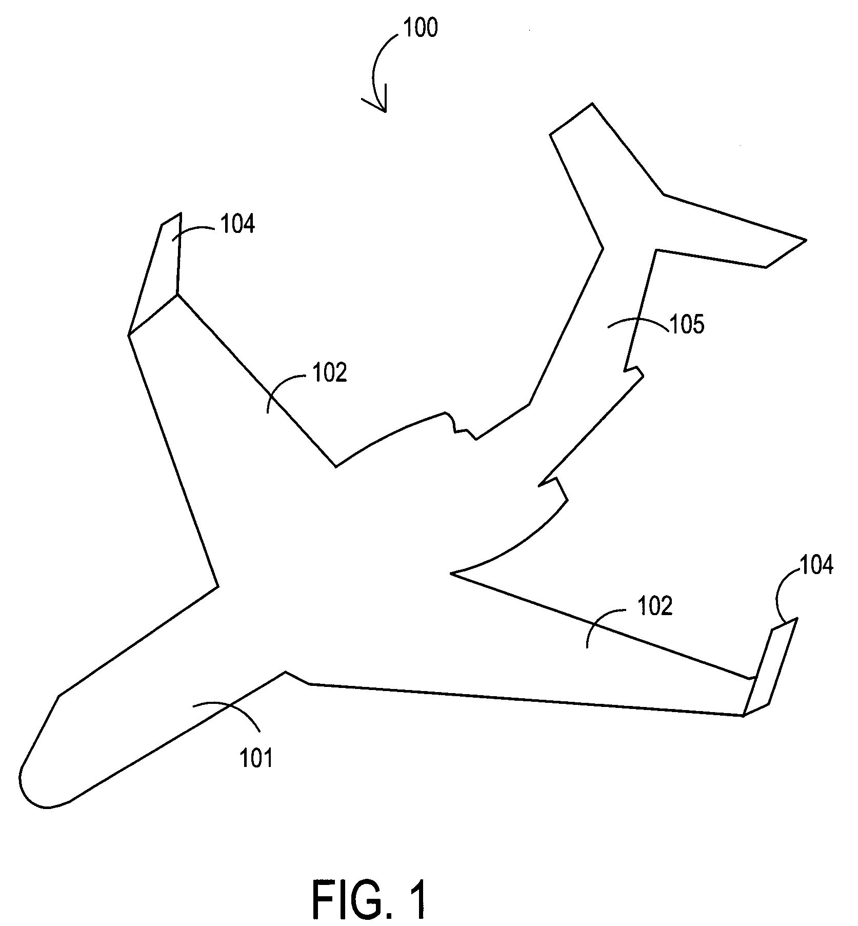
[0013]FIG. 1 shows an aircraft embodiment 100 including an aircraft having a wing with an upturned terminal winglets at the ends of the aircraft wings. As depicted, the aircraft 101 has wings 102 with upturned winglets 104 that can be used to support a high frequency line of ...


PUM


Abstract

A line of sight antenna supported in an upturned terminal winglet or similar vertical member of an aircraft is disclosed. An aperture is formed in the conductive winglet or vertical member, and the antenna is supported within the aperture by a support mechanism such that the antenna is exposed to the line of sight transmissions. A non-conductive covering may also be used for the aperture. Using the cover, the antenna within the winglet can be configured so that it does not alter the appearance or aerodynamic characteristics of the aircraft. Alternatively, the antenna can be coupled to the outside of the winglet or vertical member if cosmetics are not a concern. The frequency range of the antenna can be tuned to cover desired frequency ranges. The antenna position at the winglet maintains a large physical separation from fuselage-mounted antennas thereby reducing interference.

Description

TECHNICAL FIELD OF THE INVENTION[0001]This invention relates to a very high frequency line of sight antennas supported in an aircraft wing with an upturned terminal winglet or similar vertical member, and particularly to a winglet antenna supported in a cutaway aperture in a conductive winglet having a non-conductive covering for the aperture.BACKGROUND[0002]Certain antennas installed within aircraft exist in the prior art. However, current art aircraft antennas have a co-location interference problem with other radios and their antennas that occur, mainly due to their location in the aircraft fuselage. When antennas are added to an aircraft fuselage an extensive coupling analysis is required, and subsequent relocation of several existing antennas usually has to occur. Further, the addition of current art antennas can alter the cosmetic appearance of the aircraft, or can alter or degrade the aerodynamic characteristics of the aircraft. Other attempts to add a line of sight antenna i...

Claims


Application Information

Patent Timeline
Patent Type & Authority Applications(United States)
IPC IPC(8): B64D47/00
CPCH01Q1/287
Inventor HANUSA, JOHN H.TIGNOR, CLAUDE W.MAY, VINCENT A.REDUS, WESLEY D.STUART, SUEANNHEIN, PAUL W.
Owner L 3 COMM INTEGRATED SYST
Why Eureka
Try Eureka