Circuit System With Supply Voltage For Driving An Electromechanical Switch

a circuit system and supply voltage technology, applied in the field of voltage conversion, can solve the problems of limiting the range of operating power obtainable, heavy, bulky devices, and the character of drive circuitry capable of providing acceptable performance and package siz

Inactive Publication Date: 2008-09-04
GENERAL ELECTRIC CO
View PDF5 Cites 39 Cited by
  • Summary
  • Abstract
  • Description
  • Claims
  • Application Information

AI Technical Summary

Benefits of technology

[0007]According to numerous embodiments of the invention, a circuit is provided for controlling operation of a load. A MEMS switch is positioned in the circuit to place the load in one of a conducting state or a nonconducting state and a piezoelectric transformer provides a relatively high voltage output signal or a relatively low voltage output signal to control movement of the switch between a closed position, placing the load in the conducting state, and an open position, with the high voltage output signal including a frequency component in the resonant frequency range of the transformer. Control circuitry provides an input voltage signal to the piezoelectric transformer to provide the high voltage output signal or the low voltage output signal at the output terminals of the piezoelectric transformer. The ratio of the peak value of the high voltage output signal to the peak value of the input voltage signal may range from 5 to 10.
[0008]According to other embodiments of the invention, a circuit for supplying a drive voltage to a MEMS switch includes a piezoelectric transformer having a characteristic resonant frequency with an output terminal of the transformer coupled to the gate electrode. The drive circuitry may be coupled to energize the transformer with a first relatively low voltage signal having a frequency component different from the characteristic resonant frequency, with the first signal having a first peak voltage, in order for the transformer to provide a second signal in response to the first signal, with the second signal also having a frequency component different from the peak resonant frequency, and the second signal having a second peak voltage greater than the first peak voltage. The circuitry may include rectifying circuitry coupled between the transformer output terminal and the gate electrode to convert the second signal into a rectified signal capable of changing the state of the MEMS switch.
[0009]According to still other embodiments, a system includes a circuit having a supply voltage, a load and an electromechanical switch having an element moveable to a first position which places the switch in a conducting mode and moveable to a second position which places the switch in a non-conducting mode. The switch further includes a control terminal for selectively applying or removing an electrostatic force to place the element in the first position or in the second position. The high voltage terminal of a piezoelectric transformer is connected to the control terminal and a second terminal of the transformer is connected to receive an input signal so that with application of a first level signal to the second terminal the high voltage terminal provides a high voltage signal to the control terminal of sufficient voltage to generate an electrostatic field which displaces the element from one of the positions to the other position.
[0010]In an embodiment of a method for controlling operation of a load, a circuit is formed with a MEMS switch positioned to place the load in one of a conducting state or a nonconducting state and a piezoelectric transformer having a resonant frequency range with a peak resonant frequency. A relatively high voltage output signal or a relatively low voltage output signal is provided to output terminals of the piezoelectric transformer to control movement of the switch between a closed position and an open position, with the high voltage output signal including a frequency component in the resonant frequency range of the transformer. The input terminals of the piezoelectric transformer may be driven according to a control signal to selectively provide the high voltage output signal or the low voltage output signal at the output terminals of the piezoelectric transformer.

Problems solved by technology

As switching component sizes continue to shrink, the characteristics of drive circuitry capable of providing acceptable performance and package size is becoming more demanding.
With trends in power electronics to miniaturize components, the winding process normally results in heavy, bulky devices.
Formation of planar transformers on, for example, semiconductor substrates or PCB's is more compact, but remains complex, costly, area intensive, and limits the range of operating power obtainable.

Method used


Image

  • Circuit System With Supply Voltage For Driving An Electromechanical Switch
  • Circuit System With Supply Voltage For Driving An Electromechanical Switch
  • Circuit System With Supply Voltage For Driving An Electromechanical Switch

Examples


Embodiment Construction

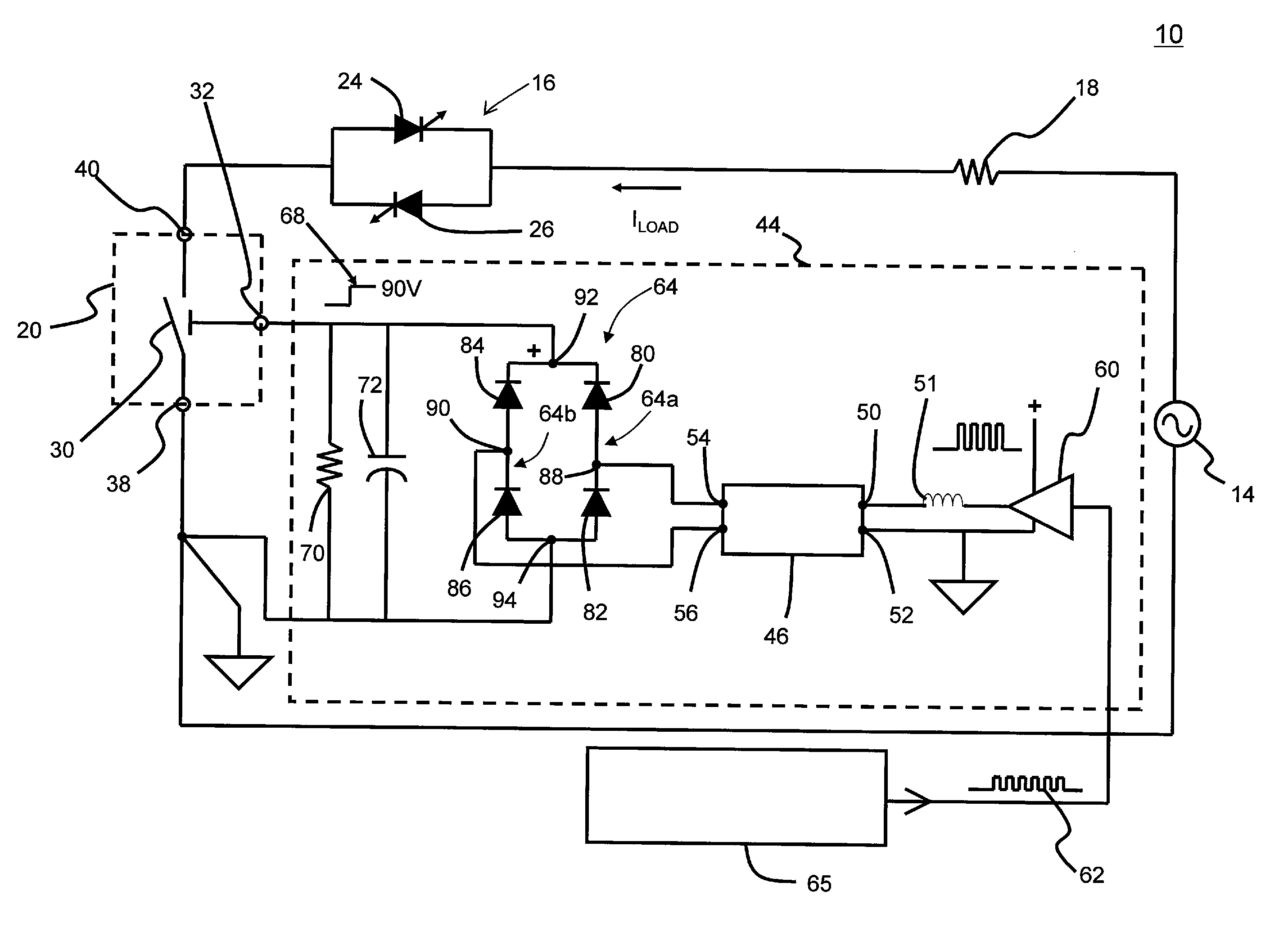
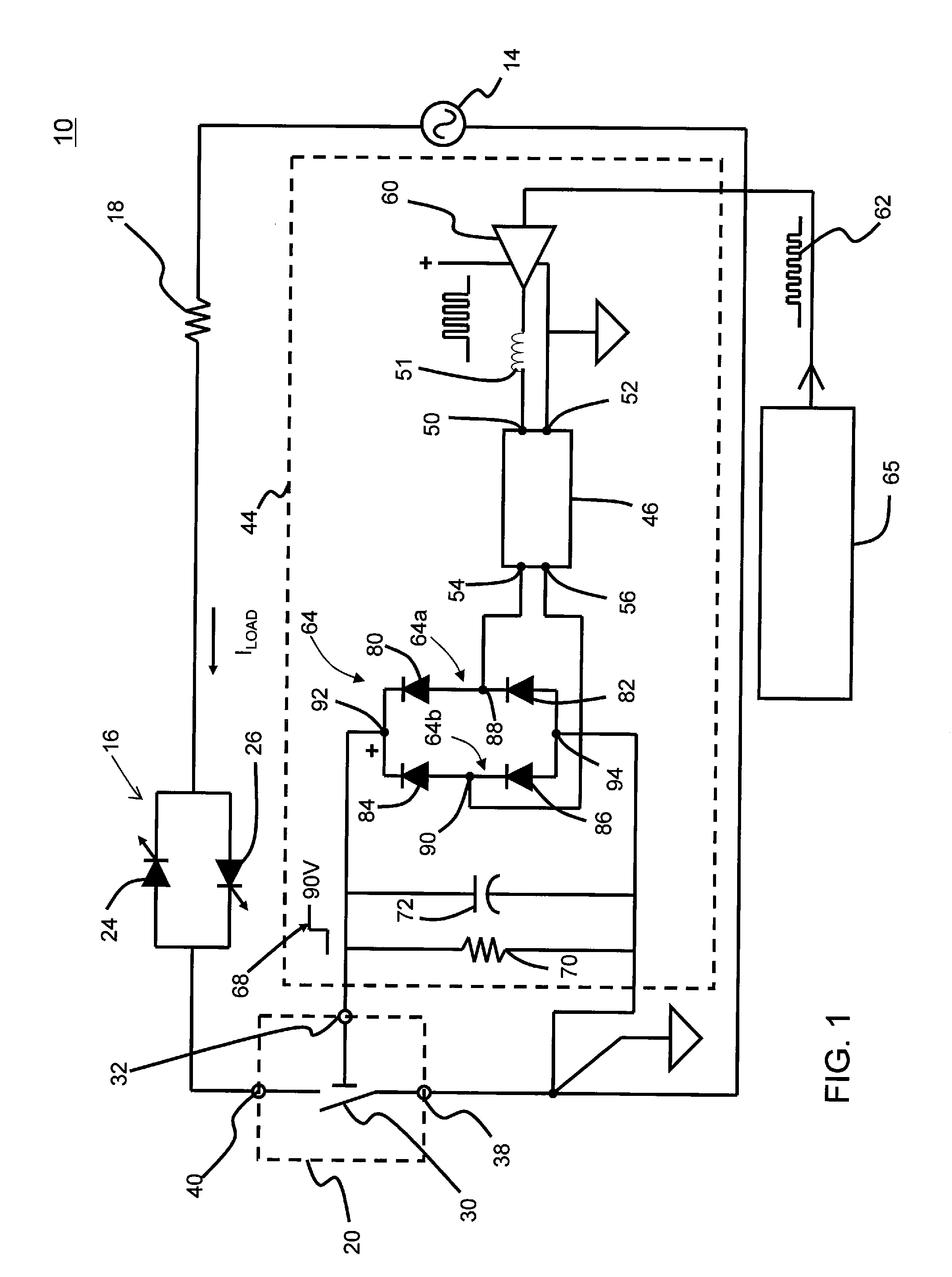
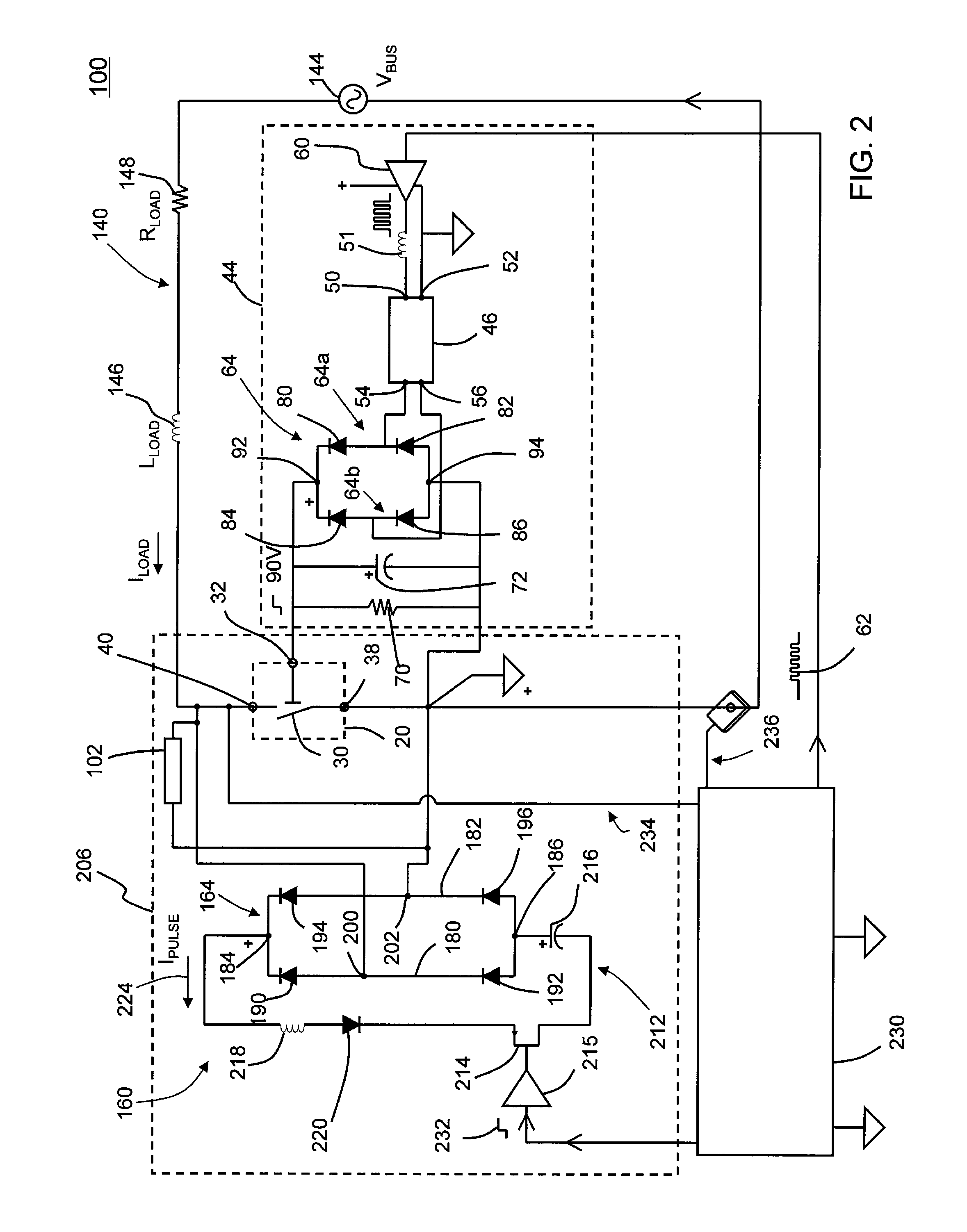
[0017]Presently, Microelectromechanical Systems (MEMS) generally refer to micron-scale structures that can, for example, integrate a multiplicity of diverse elements, e.g., mechanical elements, electromechanical elements, sensors, actuators, and electronics, on a common substrate through micro-fabrication technology. Switch technology used for MEMS applications includes semiconductor devices such as power Field Effect Transistors (FETs) and Insulated Gate Bipolar Transistors (IGBTs), but also includes MEMS switches which are electromechanical in nature. One example of a MEMS switch includes a gate electrode controlling an electrostatically actuated beam. The beam is displaceable between two positions to render the switch in either a conductive or a non-conductive state.

[0018]Such MEMS switches have substantially different requirements than semiconductor switches which typically require a low voltage actuating gate drive, e.g., less than 18V. Present MEMS switches, on the other hand,...


PUM


Abstract

A circuit for controlling operation of a load. In one example, a MEMS switch is positioned in the circuit to place the load in one of a conducting state or a nonconducting state. A piezoelectric transformer provides a relatively high voltage output signal or a relatively low voltage output signal to control movement of the switch between a closed position, placing the load in the conducting state, and an open position. The high voltage output signal includes a frequency component in the resonant frequency range of the transformer. Control circuitry provides an input voltage signal to the piezoelectric transformer to provide the high voltage output signal or the low voltage output signal at the output terminals of the piezoelectric transformer.

Description

BACKGROUND OF THE INVENTION[0001]1. Field of Invention[0002]The present invention relates generally to voltage conversion and, more specifically, to circuits and systems incorporating current loads and switches for controlling current flow therein.[0003]2. Description of the Prior Art[0004]Electromechanical switches are typically gated into the conducting or nonconducting states using switched DC voltage supplies or switched AC supplies. Numerous applications require very fast switching characteristics which are attainable with microelectromechanical (MEMS) switches. Such switches have distinct voltage and current characteristics and can attain switching speeds on the order of 3 to 20 microseconds. As switching component sizes continue to shrink, the characteristics of drive circuitry capable of providing acceptable performance and package size is becoming more demanding.[0005]Wire wound electromagnetic transformers are commonly used for voltage conversion in many power circuit appl...

Claims


Application Information

Patent Timeline
Patent Type & Authority Applications(United States)
IPC IPC(8): H01L41/107
CPCH01H1/0036H01H2071/008H01H59/0009B81B7/02H01H9/54
Inventor WRIGHT, JOSHUA ISAACSUBRAMANIAN, KANAKASABAPATHIREEVES, NICOLE CHRISTINEPARK, JOHN NORTON
Owner GENERAL ELECTRIC CO
Why Eureka
Try Eureka