System for voltage stabilization of power supply lines

a power supply line and voltage stabilization technology, applied in the field of voltage stabilization, can solve the problems of undersized conductor losses, excessive voltage drop, inadequate voltage levels of electric power connected to the lines, etc., and achieve the effect of adequate voltage and increased energy us

Inactive Publication Date: 2007-02-20
MAGTECH AS (NO)
View PDF40 Cites 13 Cited by
  • Summary
  • Abstract
  • Description
  • Claims
  • Application Information

AI Technical Summary

Benefits of technology

[0021]Embodiments of the invention permit existing weak lines to be adapted to maintain adequate voltage in a simple and inexpensive manner when there is an increase in energy use. In one embodiment, adequate voltage is maintained by connecting the voltage stabilization system in the line between the distribution transformer and the users. In a version on the embodiment, the autotransformer adds a voltage in series with the supply voltage, thus enabling the line voltage to be stabilized. The variable inductance regulates the voltage across the inductance (by altering the permeability of the inductance core by means of orthogonal fields), or the time voltage integral across it, in order to regulate the voltage across the series winding in the autotransformer.

Problems solved by technology

Excessive voltage drop will result from the losses caused by undersized conductors.
The excessive voltage drop results in inadequate voltage levels for the electric power connected to the lines.
A fixed transformer ratio may result in a voltage that is too low, (i.e., an undervoltage) when the load is high, and a voltage that is too high, (i.e., an overvoltage condition) when the load is low.
Because the load is dependent at all times on the highly variable requirements of individual electric power consumers, fixed ratio transformers are often inadequate to serve a dynamic load.
This approach results in a longer interruption in service when compared with the preceding approach.
However, mechanically controlled variacs, generally, are no longer used because the mechanical components required frequent service.
This approach is also undesirable because of the large scope of work required to relocate electric lines and the high cost associated with such a project.
However, the power handling capability of the device is limited because the regulator described in Wanlass is meant for operation in the non-saturated area of the core, and the permeability range is limited to the linear region of the core.

Method used


Image

  • System for voltage stabilization of power supply lines
  • System for voltage stabilization of power supply lines
  • System for voltage stabilization of power supply lines

Examples


first embodiment

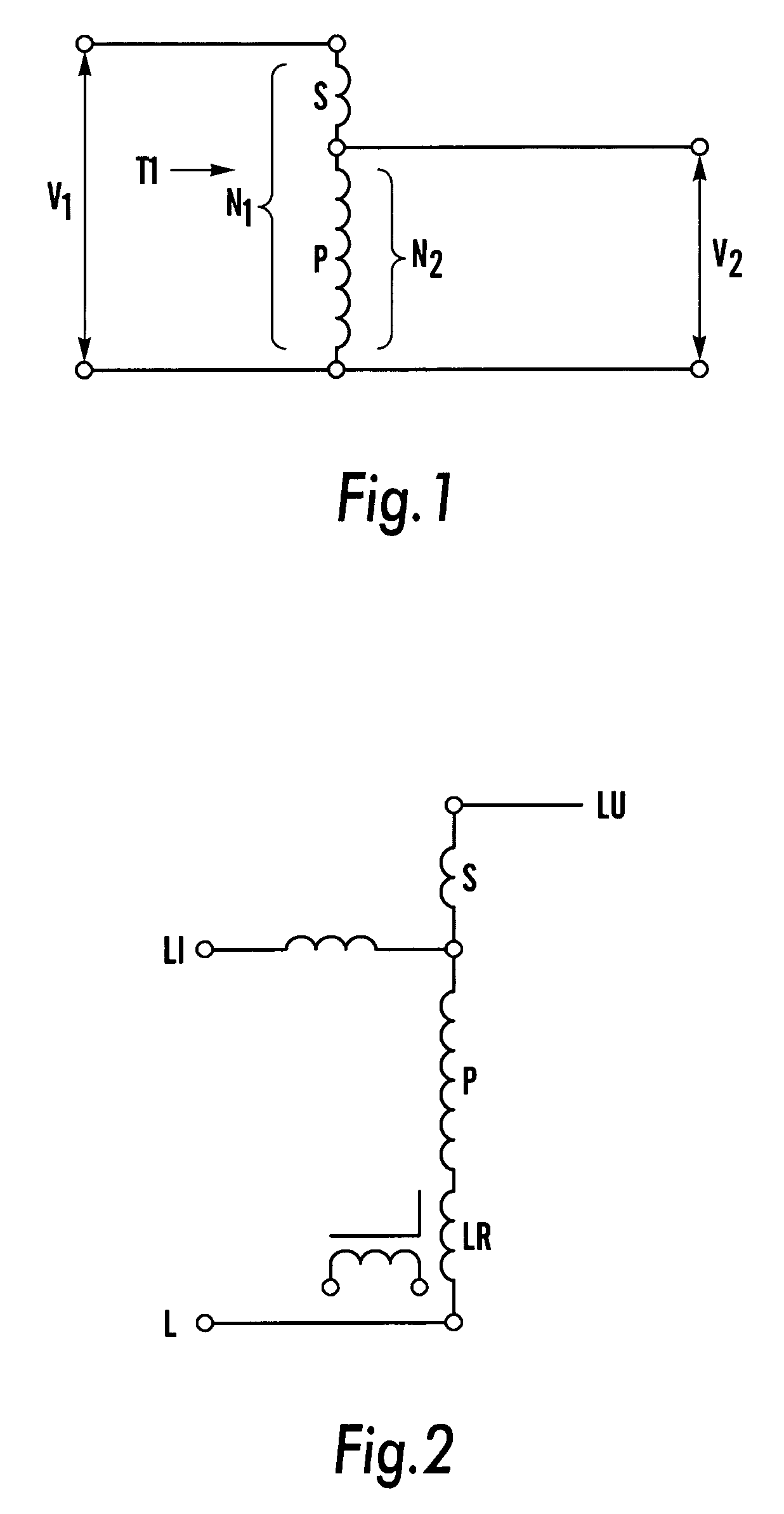
[0042]In the invention shown in FIG. 2, the series winding S is connected in series with a first power supply line (e.g., a first phase) from the line input LI to the line output LU. In this embodiment, the parallel winding is connected to a second power supply line (e.g., a second phase) L via an orthogonal field variable inductance LR. The voltage in the series winding S can be changed here by changing the voltage in the parallel winding P by means of the variable inductance LR.

second embodiment

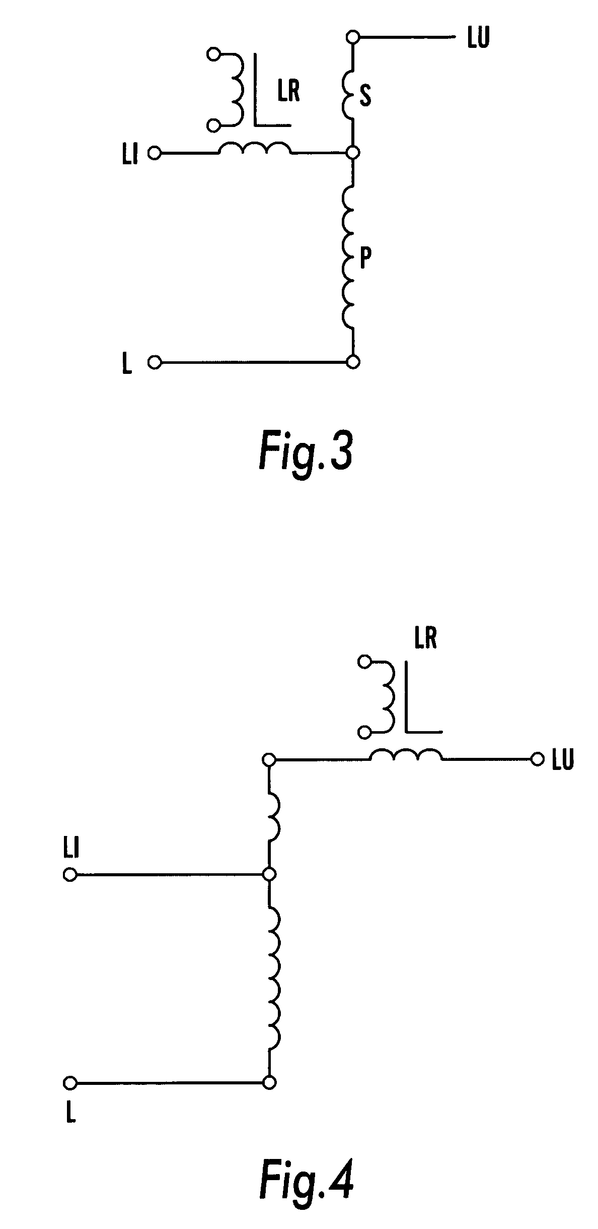
[0043]In the invention shown in FIG. 3, the variable inductance LR and the series winding S are connected in series with the first power supply line from LI to LU, with the variable inductance connected to the line side LI of the series winding S. The parallel winding P is connected to the second power supply line.

third embodiment

[0044]In the invention shown in FIG. 4, the variable inductance LR and the series winding S are connected in series with the power supply line from LI to LU, with the variable inductance connected to the load side LU of the series winding S. The parallel winding is connected directly to the second power supply line L. In versions of the preceding embodiments, the second phase is a neutral conductor.

[0045]In the second and the third embodiments of the invention, the voltage in the first power supply line LI–LU will be changed because the variable inductance LR absorbs a time voltage integral that remains in series with the voltage from the series winding S of the autotransformer.

[0046]Because the voltage absorbed by the variable inductance is a reactive voltage, the voltage leads the current by 90°. As a result, the voltage to be subtracted or added to the load voltage is 90° out of phase with a resistive current drawn by the load. In the autotransformer there is an ampere-turn balan...


PUM


Abstract

The invention relates to a voltage stabilization system for power supply lines, comprising a variable inductance, an autotransformer and a system for controlling the variable inductance to automatically compensating for voltage variations of the power supply lines. The system can include a control system that includes a processor unit, a setpoint adjustment unit, a feedback unit and a rectifier circuit.

Description

CROSS-REFERENCE TO RELATED APPLICATIONS[0001]This application claims the benefit under 35 U.S.C. § 119(e) of U.S. Provisional Application No. 60 / 433,601, filed Dec. 16, 2002, and claims priority to Norwegian Patent Application No. 2002 5990 filed on Dec. 12, 2002. The entire contents of these two applications are incorporated herein by reference.FIELD OF THE INVENTION[0002]The present invention relates generally to voltage stabilization. More particularly, the invention relates to methods and systems that employ a variable inductance to compensate for voltage variations that may arise in power supply lines.BACKGROUND OF THE INVENTION[0003]Undersized lines for electric power transmission, also referred to as “weak lines”, have too small a conductor cross section in relation to the load requirements and a relatively high resistance. Excessive voltage drop will result from the losses caused by undersized conductors. The excessive voltage drop results in inadequate voltage levels for th...

Claims


Application Information

Patent Timeline
Patent Type & Authority Patents(United States)
IPC IPC(8): H02J3/24H02J3/00G05F1/38H02PH02P13/12
CPCG05F1/38
Inventor HAUGS, ESPENSTRAND, FRANKTJELDHORN, REIDAR
Owner MAGTECH AS (NO)
Why Eureka
Try Eureka