Optical lens device solderable to substrate and method of manufacturing the optical lens device

a technology of optical lens and substrate, which is applied in the direction of instruments, metal-working devices, mountings, etc., can solve the problems of increasing costs, increasing costs, and all products may be defective, so as to reduce the amount of gold used, and reduce the cost

Inactive Publication Date: 2008-09-04
ALPS ALPINE CO LTD
View PDF2 Cites 2 Cited by
  • Summary
  • Abstract
  • Description
  • Claims
  • Application Information

AI Technical Summary

Benefits of technology

[0014]The method of manufacturing an optical lens device according to the first aspect of the present invention includes the steps of forming the lens barrel into the shape of a quadrangular prism having corners that have a shape having a radius of curvature or that are chamfered, and installing the lens into the lens barrel; disposing in parallel a plurality of the lens barrels in which a plurality of the lenses are installed; masking the lens at one side face of each lens barrel disposed in parallel, and the vicinity of the lens; and depositing a gold layer by sputtering on the one side face of each masked lens barrel, including the corners. Therefore, since each gold layer can be formed on only one side face required for soldering and the corners at both sides thereof, the amount of gold used can be reduced. In addition, since each gold layer can be formed after forming the lens, each gold layer need not be made thick in consideration of each gold layer being subjected to high temperature. Accordingly, even due to this, the amount of gold used can be reduced, so that costs can be reduced. Still further, for an optical lens device in which a lens and an edge portion are integrally formed using glass, similar effects can be obtained.
[0015]In addition, according to the method of manufacturing an optical lens device according to the first form of the present invention, a titanium layer and a platinum layer are formed on the one side face of each masked lens barrel or one side face of a masked edge portion, and the gold layer is deposited thereon. Therefore, good adhesion of each gold layer can be achieved, so that sufficient soldering strength can be ensured.
[0016]Still further, according to the optical lens device according to the third aspect of the present invention, the lens barrel is formed into the shape of a quadrangular prism having corners that have a shape having a radius of curvature or that are chamfered, and a gold layer is disposed on only one side face of the lens barrel, including the corners. Accordingly, since the gold layer is formed on only one side face of the lens barrel and the corners, it is possible to reduce costs by reducing the amount of gold used. In addition, for an optical lens device in which a lens and an edge portion are integrally formed using glass, similar effects can be obtained.
[0017]Still further, according to the optical lens device according to the first form of the present invention, a titanium layer and a platinum layer are disposed on the one side face of the lens barrel or one side face of an edge portion so as to be disposed below the gold layer. Therefore, good adhesion of the gold layer can be achieved, so that sufficient soldering strength can be ensured.

Problems solved by technology

Therefore, when a problem arises, all products may be defective.
This increases costs.
When plating is performed on other faces, costs are further increased.

Method used


Image

  • Optical lens device solderable to substrate and method of manufacturing the optical lens device
  • Optical lens device solderable to substrate and method of manufacturing the optical lens device
  • Optical lens device solderable to substrate and method of manufacturing the optical lens device

Examples


Embodiment Construction

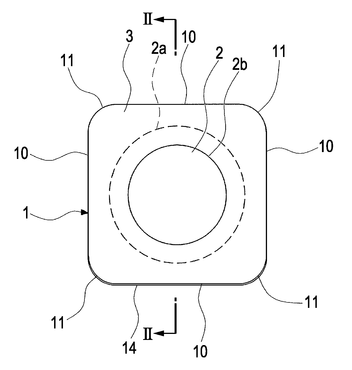
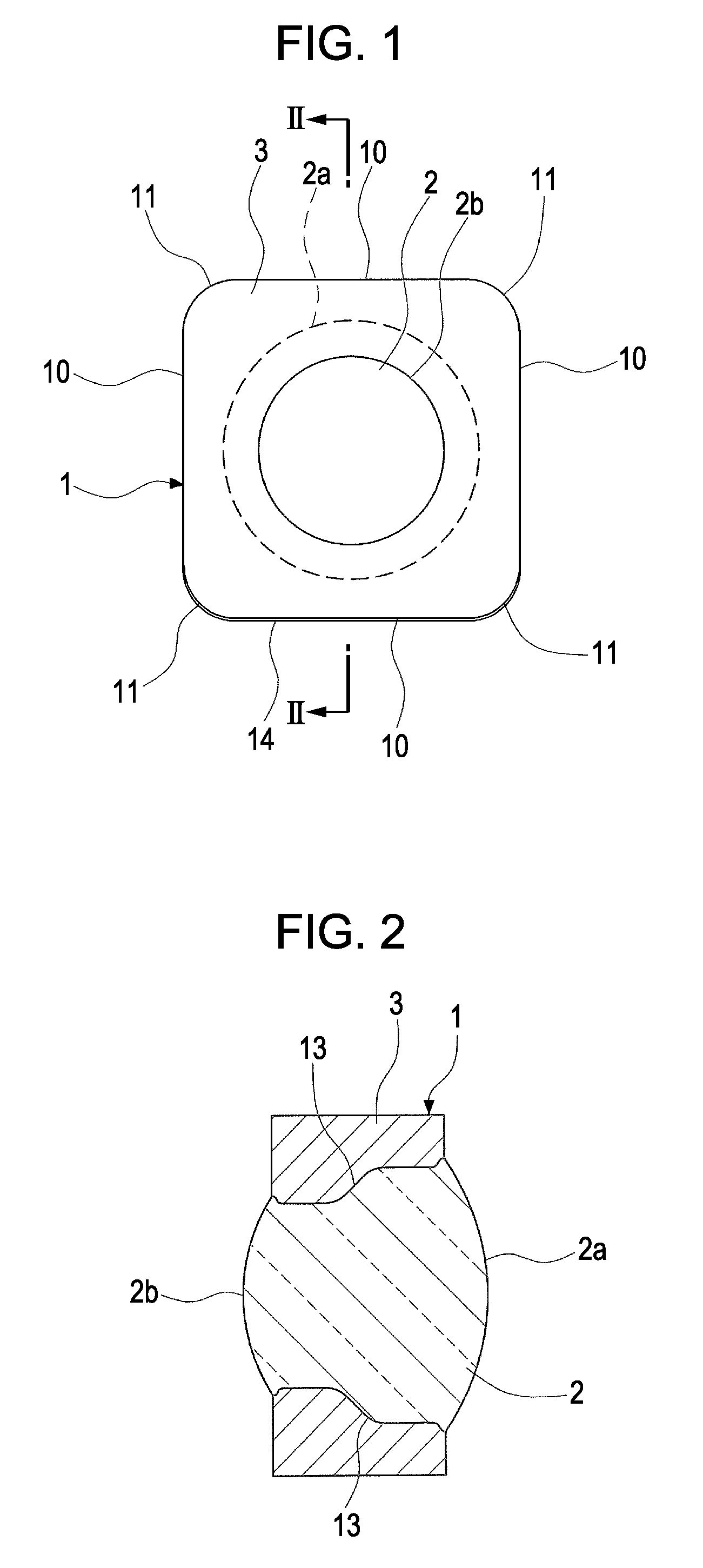
[0022]An embodiment of the present invention will now be described in detail with reference to the drawings. FIG. 1 is a front view of an optical lens device according to the embodiment of the present invention. FIG. 2 is a sectional view taken along line II-II shown in FIG. 1. As shown in FIG. 1, in an optical lens device 1 according to the embodiment, a glass lens 2 is accommodated in a metallic lens barrel 3.

[0023]As shown in FIGS. 1 and 2, the lens barrel 3 has an external shape of a quadrangular prism. The lens barrel 3 has four side faces 10. Portions between the side faces 10 have shapes having a radius of curvature (hereafter referred to as “R shapes”), so that four corners 11 are formed. The corners 11 are not limited to those having R shapes. The corners 11 may be chamfered by being linearly cut. In addition, as shown in FIG. 2, the internal portion of the lens barrel 3 is formed into a cylindrical shape that can accommodate the lens 2, and steps 13 are formed at intermedi...


PUM

PropertyMeasurementUnit
radius of curvatureaaaaaaaaaa
temperatureaaaaaaaaaa
thicknessesaaaaaaaaaa

Abstract

A method of manufacturing an optical lens device includes the steps of forming a lens barrel into the shape of a quadrangular prism having corners that have a shape having a radius of curvature or that are chamfered, and installing a lens into the lens barrel; disposing in parallel a plurality of the lens barrels in which a plurality of the lenses are installed; masking the lens at one side face of each lens barrel disposed in parallel, and the vicinity of the lens; and depositing a gold layer by sputtering on the one side face of each masked lens barrel, including the corners.

Description

CLAIM OF PRIORITY[0001]This application claims benefit of the Japanese Patent Application No. 2007-037834 filed on Feb. 19, 2007, which is hereby incorporated by reference.BACKGROUND OF THE INVENTION[0002]1. Field of the Invention[0003]The present invention relates to an optical lens device that has an edge portion or a lens barrel at a periphery of a lens and that is solderable to a substrate, and to a method of manufacturing the optical lens device. More particularly, the present invention relates to an optical lens device in which a gold layer is formed only on one side face of an edge portion or of a lens barrel, and to a method of manufacturing the optical lens device.[0004]2. Description of the Related Art[0005]In an optical lens device having a glass lens accommodated in a metallic lens barrel, a gold layer may be required in the lens barrel or an edge portion, to solder the optical lens device to a substrate. Hitherto, the gold layer is formed by electrolytic gold plating af...

Claims


Application Information

Patent Timeline
Patent Type & Authority Applications(United States)
IPC IPC(8): G02B7/02B23P15/00
CPCY10T29/49904G02B7/02
Inventor HATAKEYAMA, SHIGERU
Owner ALPS ALPINE CO LTD
Why Eureka
Try Eureka