Method for loading a medical device into a delivery system

Active Publication Date: 2008-09-04
WILLIAM COOK EURO +1
View PDF85 Cites 16 Cited by
  • Summary
  • Abstract
  • Description
  • Claims
  • Application Information

AI Technical Summary

Benefits of technology

[0008]Disclosed herein is a method for loading a medical device into a delivery system. Preferably, the medical device is loaded into the delivery system with minimal frictional forces during loading an

Problems solved by technology

Consequently, the stent may buckle or collapse during the loading process instead of sliding smoothly into the sheath.
The recoiling of the stent o

Method used


Image

  • Method for loading a medical device into a delivery system
  • Method for loading a medical device into a delivery system
  • Method for loading a medical device into a delivery system

Examples


example 1

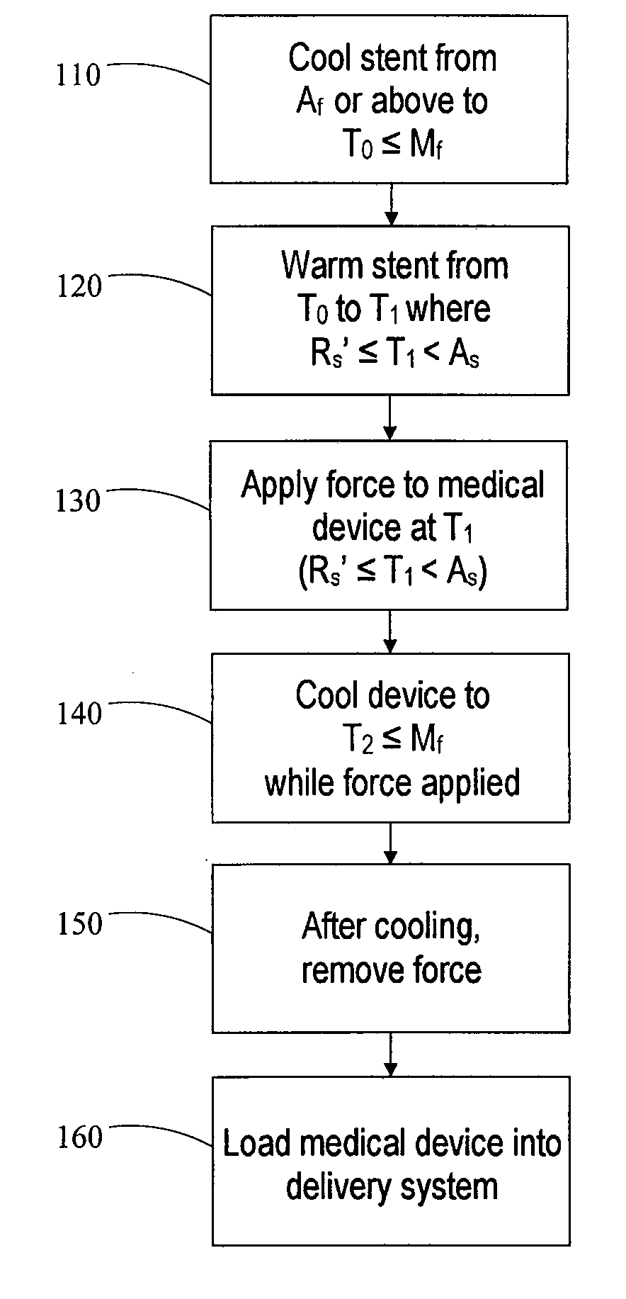
[0097]A self-expanding stent comprising a nickel-titanium shape memory alloy having transformation temperatures within the ranges given in Table 1 is loaded into a transfer tube. The steps of the exemplary loading process described in this example are shown schematically in FIG. 3B.

[0098]First, the stent is heated 100 to a temperature at or above the austenite finish temperature Af of the shape memory alloy. After equilibrating in an environment maintained at a temperature of about 40° C., which is above Af, the stent is transported to an enclosed environment (“cold box”) maintained at a temperature of about 10° C. The stent is then immersed in liquid nitrogen having a temperature of about −196° C. for several seconds to cool 110 the stent and induce a phase transformation to martensite. The immersion is carried out in a liquid-nitrogen filled container having dimensions large enough to completely submerge the stent. Additional liquid nitrogen may flow into the container periodicall...

example 2

[0103]Self-expanding stents comprising a nickel-titanium shape memory alloy having the transformation temperatures given in Table 2 are loaded into transfer tubes in a series of tests (Experiments 1.1 to 3.2) described below. The results of the tests are summarized in Table 3.

TABLE 2TransformationApproximate Value forTemperatureStents of Example 2 (° C.)Af29As20Rs26.5R′f~20-30Rf15R′s2.5Ms−34Mf−85

[0104]In the experiments, each stent is heated or cooled to a temperature within a specified R-phase temperature range, and then compressed as described in Example 1 at that temperature. The structure of each stent is thus partially or fully R-phase prior to compression. The impact of the training step (cooling prior to release of the compressive force) on the loading process is explored in the experiments.

experiment 1.1

[0105]Stent Warmed to R′s>T>R′f for Compression

[0106]For this experiment, the loading procedure is carried out as follows. First, the stent is immersed in liquid nitrogen until the stent attains a temperature of about −196° C. Next, the stent is allowed to warm up to a temperature of greater than R′s of the shape memory alloy but less than R′f. Within this temperature regime, it is expected that stent includes both martensite and R-phase. The stent is then compressed using approximately 10 lbs of force. During the compression, the stent is dipped in liquid nitrogen for about 40 seconds. The stent is removed from the liquid nitrogen and the force is released. Finally, the stent is loaded into a tube having an internal diameter of 1.65 mm. The experiment is carried out using two different stents, each measuring 7 mm (expanded diameter)×140 mm (length).

[0107]During the loading procedure using the first stent (#151123-2), the cold box is maintained at a temperature of about 7.3° C. A th...


PUM

PropertyMeasurementUnit
Timeaaaaaaaaaa
Forceaaaaaaaaaa
Temperatureaaaaaaaaaa

Abstract

A process to load a medical device comprising a shape memory material into a delivery system is described herein. According to one aspect, the method includes applying a force to the medical device to obtain a delivery configuration thereof, where the device is at a first temperature within an R-phase temperature range of the shape memory material during application of the force. The medical device is cooled in the delivery configuration to a second temperature at or below a martensite finish temperature of the shape memory material. The force is then removed from the medical device, and the device is loaded into a delivery system. Preferably, the medical device substantially maintains the delivery configuration during the loading process.

Description

RELATED APPLICATIONS[0001]The present patent document claims the benefit of the filing date under 35 U.S.C. §119(e) of Provisional U.S. Patent Application Ser. No. 60 / 872,692, filed Dec. 4, 2006, which is hereby incorporated by reference.[0002]The present patent document is related to U.S. patent application serial number 60 / ______, entitled “Method of Characterizing Phase Transformations in Shape Memory Materials,” which was filed on Dec. 4, 2007, and is hereby incorporated by reference.TECHNICAL FIELD[0003]This disclosure is related to a method of preparing an intraluminal medical device for insertion into a body lumen. More particularly, this disclosure is related to a method of loading a medical device into a delivery system.BACKGROUND[0004]One type of intraluminal medical device that is well-known in the medical profession is a self-expanding stent. Self-expanding stents are often used to treat blockages, occlusions, narrowing ailments and other related problems that restrict f...

Claims


Application Information

Patent Timeline
IPC IPC(8): A61F2/04
CPCA61F2/95A61F2002/9522A61F2210/0014A61F2250/0042Y10T29/4976C22F1/006C22F1/10Y10T29/49865C22F1/00A61F2/9522
Inventor MAGNUSON, MARK A.PARKER, FRED T.HANSEN, PALLE M.
Owner WILLIAM COOK EURO
Why Eureka
Try Eureka