Method for operating a delta wound three-phase permanent magnet brushless motor

a brushless motor and three-phase technology, applied in the direction of motor/generator/converter stopper, dynamo-electric gear control, dynamo-electric converter control, etc., can solve the problem of reducing the possibility of demagnetization of the permanent magnet of the rotor of the motor

Active Publication Date: 2008-09-11
DELPHI TECH INC +1
View PDF5 Cites 4 Cited by
  • Summary
  • Abstract
  • Description
  • Claims
  • Application Information

AI Technical Summary

Benefits of technology

[0005]Several benefits and advantages are derived from the method of the invention. In one example, reducing the requested phase current of the motor controller, when the delta wound three-phase permanent magnet brushless motor is operating in the second or fourth quadrant at a particular motor speed above the transition motor speed, reduces the possibility for demagnetization of the permanent magnets of the rotor of the motor. In the same or a different example, reducing the requested phase current of the motor controller, when the delta wound three-phase permanent magnet brushless motor is operating in the second or fourth quadrant at a particular motor speed above the transition motor speed, reduces the possibility for causing excessive thermal stress in the motor and the motor controller. In the same or a different example, having a motor controller which uses a single current sense resistor reduces the complexity and expense of motor current sensing.

Problems solved by technology

In one example, reducing the requested phase current of the motor controller, when the delta wound three-phase permanent magnet brushless motor is operating in the second or fourth quadrant at a particular motor speed above the transition motor speed, reduces the possibility for demagnetization of the permanent magnets of the rotor of the motor.

Method used


Image

  • Method for operating a delta wound three-phase permanent magnet brushless motor
  • Method for operating a delta wound three-phase permanent magnet brushless motor
  • Method for operating a delta wound three-phase permanent magnet brushless motor

Examples


Embodiment Construction

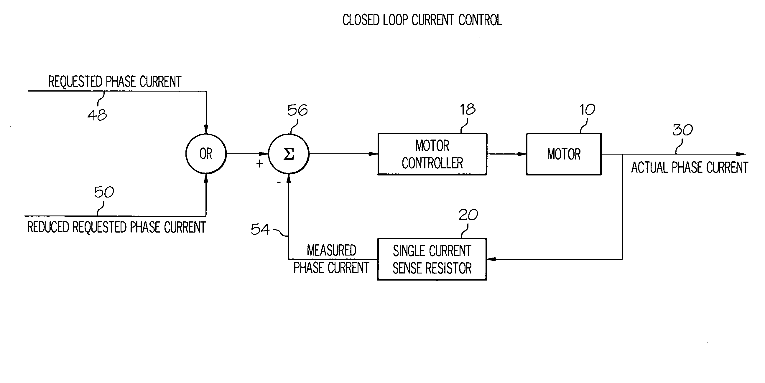
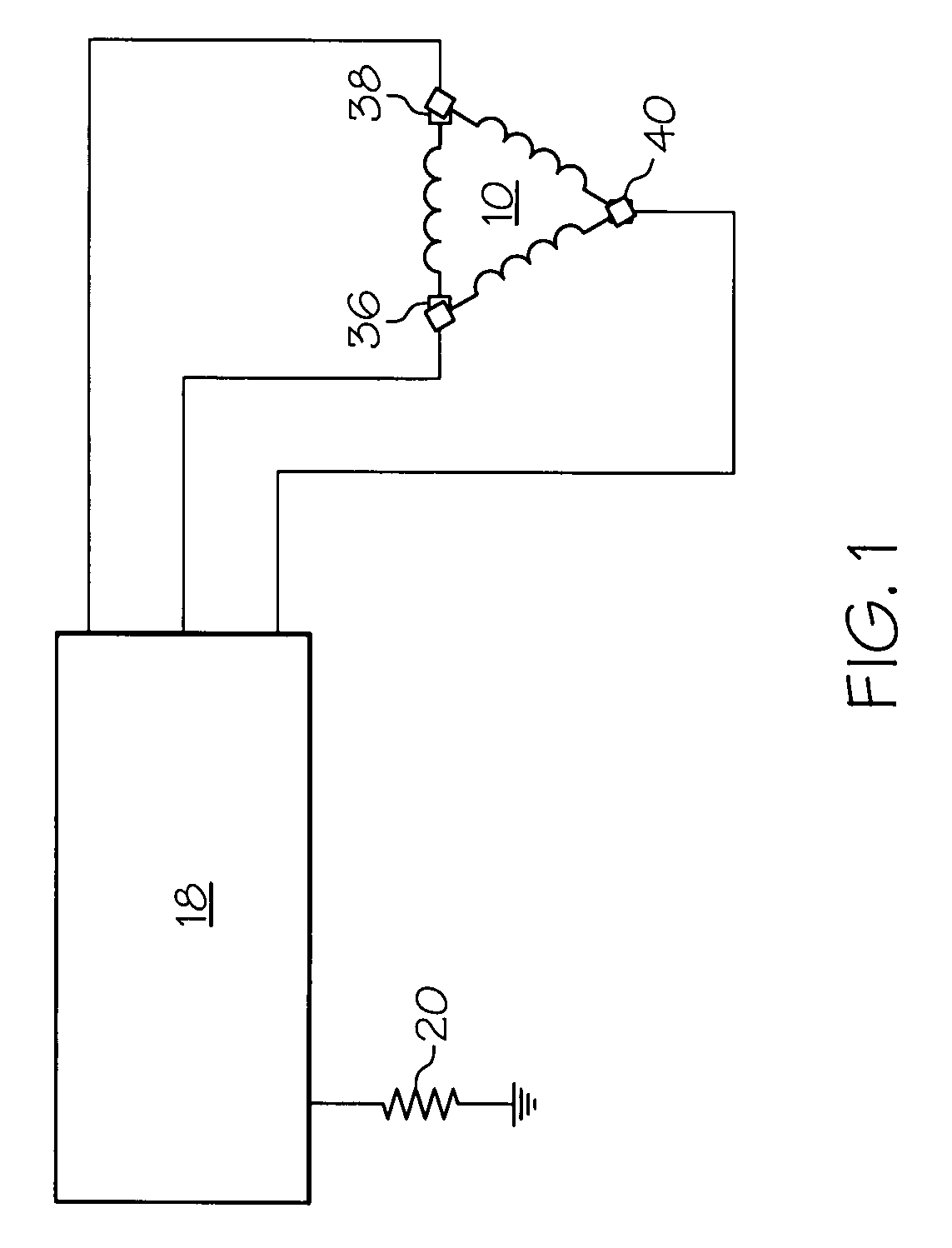
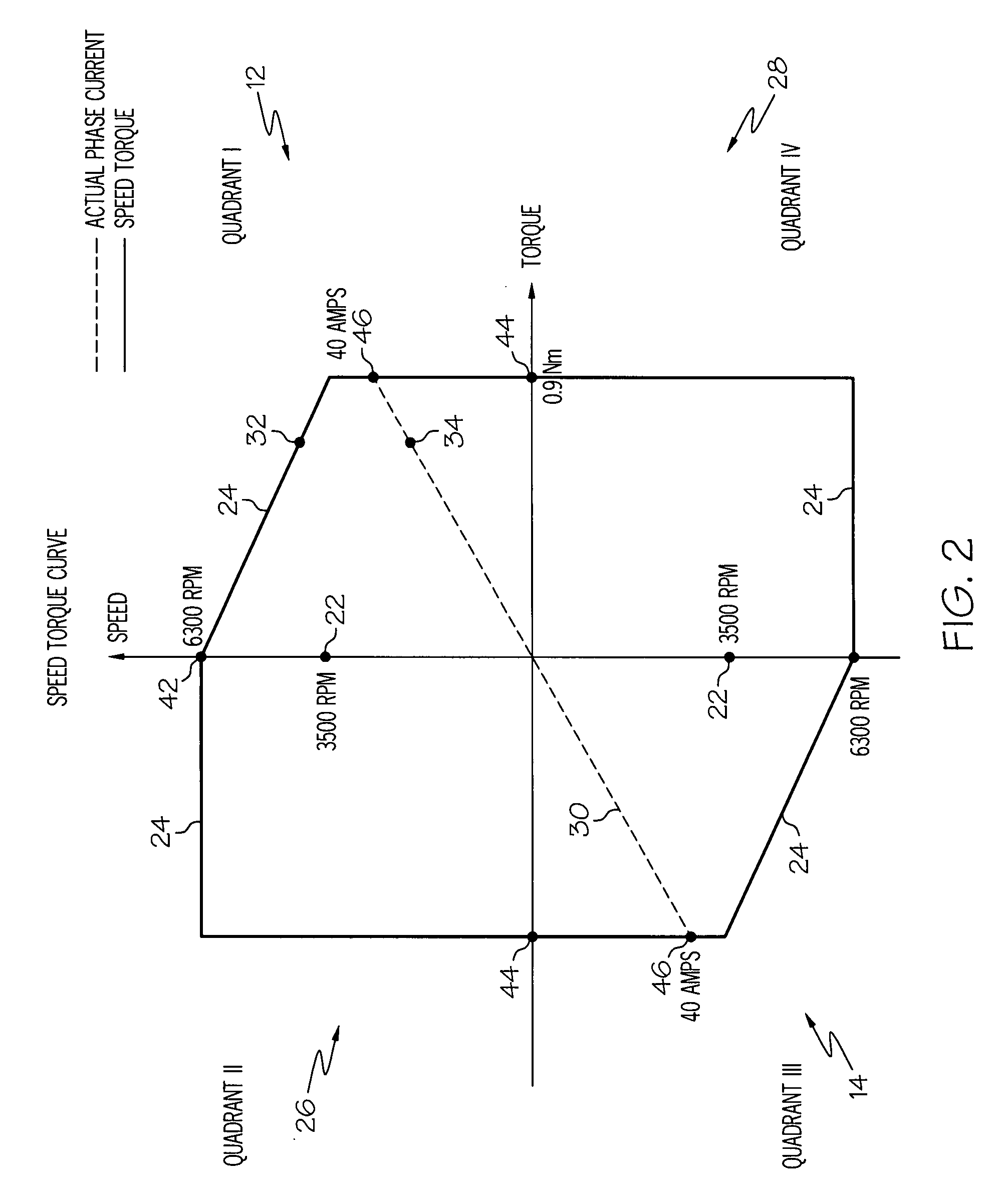
[0010]Referring to FIGS. 1-4, a method of the invention is for operating a delta wound three-phase permanent magnet brushless motor 10 and includes steps a) through c). Step a) includes determining a transition motor speed 22 of the motor 10 in a quadrant 12, 26, 14 and 28 of a motor speed versus motor torque curve 16 of the motor 10 above which motor speed 24 continues to increase while motor current / torque decreases wherein actual phase current 30 supplied to the motor 10 can be controlled by a motor controller 18 in a current control modification manner which reduces requested phase current 48 for the motor 10. Step b) includes determining the current control modification manner for a quadrant 12, 26, 14 and 28 of the motor speed versus motor torque curve 16, wherein the motor controller 18 can use the current control modification manner to reduce the requested phase current 48 to control the actual phase current 30 when the motor speed 24 is above the transition motor speed 22. ...


PUM


Abstract

Method for operating a delta wound three-phase permanent magnet brushless motor. A transition speed is determined in a quadrant of a speed versus torque curve above which speed continues to increase while current / torque decreases wherein actual phase current can be controlled in a current control modification manner which reduces requested phase current. The modification manner is determined for a quadrant, wherein a controller can use the modification manner to reduce the requested phase current to control the actual phase current when the speed is above the transition speed. The motor is controlled in a quadrant wherein, when the motor has a speed above the transition speed, the controller reduces the requested phase current in the modification manner and the controller supplies the actual phase current to the motor using the reduced requested phase current and using measured phase current of the motor derived from using a single current sense resistor.

Description

TECHNICAL FIELD[0001]The present invention relates generally to motors, and more particularly to a method for operating a delta wound three-phase permanent magnet brushless motor.BACKGROUND OF THE INVENTION[0002]Conventional motors include delta wound three-phase permanent magnet brushless motors. Conventional motor controllers for delta wound three-phase permanent magnet brushless motors monitor current for the motor based at least on a measured phase current, wherein the measured phase current is derived from using a single current sense resistor. See U.S. Pat. No. 6,262,544. The motor controller uses the measured phase current to control the amount of current supplied to the motor. However, after each motor commutation, the current measurement derived from a single current sense resistor provides an inaccurately low measured phase current due to recirculating currents in the motor windings. The winding topology of a delta wound three-phase permanent magnet brushless motor allows ...

Claims


Application Information

Patent Timeline
Patent Type & Authority Applications(United States)
IPC IPC(8): H02P21/00
CPCH02P6/001H02P6/34H02P7/281H02P23/0086H02P23/06H02P6/15H02P29/032
Inventor CYRAN, CURTIS P.DISSER, ROBERT J.
Owner DELPHI TECH INC
Why Eureka
Try Eureka