Multilevel inverter using cascade configuration and control method thereof

a multi-level inverter and cascade configuration technology, applied in the field of high-voltage inverters, can solve the problems of burning out and the inability to drive the multi-level inverter using the cascade configuration

Active Publication Date: 2008-09-11
LS IND SYETEMS CO LTD
View PDF12 Cites 27 Cited by
  • Summary
  • Abstract
  • Description
  • Claims
  • Application Information

AI Technical Summary

Benefits of technology

The present invention provides a multilevel inverter with a cascade configuration that has a device to control the power factors of the unit cells. This prevents the occurrence of voltage convergence in a specific cell when the motor or a small load is decelerating. By controlling each cell to have the same power factor, the invention ensures a more stable and efficient operation of the inverter.

Problems solved by technology

The technical problem addressed in this patent is the need to improve the performance and reliability of a multilevel inverter using a cascade configuration, by reducing the required provision of secondary windings and compensating for power factor differences that can cause voltage regeneration in each power cell to change upon controlling a motor to be decelerated.

Method used


Image

  • Multilevel inverter using cascade configuration and control method thereof
  • Multilevel inverter using cascade configuration and control method thereof
  • Multilevel inverter using cascade configuration and control method thereof

Examples


Embodiment Construction

[0022]The objects and configurations and operational effects of the present invention to achieve the objects will be understood more clearly from the following description of the preferred embodiments of the present invention with reference to the accompanying drawings.

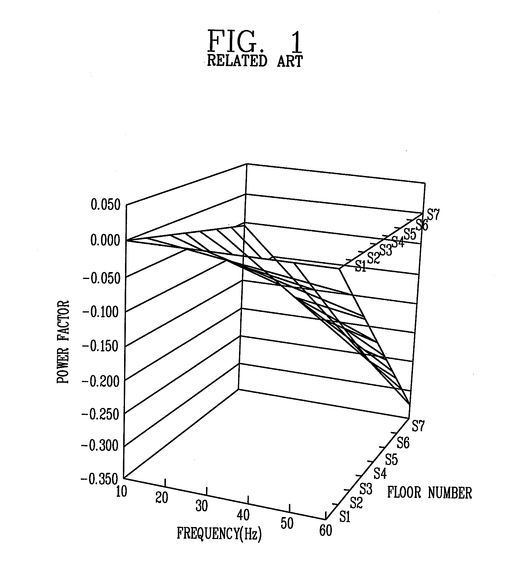
[0023]First, FIG. 1 shows the interrelation among the output frequency, the floor number of a power cell and the power factor, which shows that the power factor changes according to the output frequency and the floor number of the power cell in a multilevel inverter using a cascade configuration.

[0024]As shown in FIG. 1, it can be seen that as the output frequency becomes higher, the power factor of a power cell decreases. It can also be seen that the power factor decreases, according to the floor numbers of serially connected power cells for each phase of a three-phase AC (Alternating Current), namely, as the floor number (i.e., the connected sequence) becomes farther away from the input power source.

[0025]On the oth...


PUM


Abstract

A multilevel inverter using a cascade configuration with a device for equally controlling a power factor for each unit cell includes: a master controller, a plurality of power cells connected in series for each of three AC (Alternating Current) phases, a phase shift transformer for supplying a power cell input voltage, a CAN (Controller Area Network) communication network to provide a communication path between the master controller and each power cell, and cell controllers to control output voltages and output frequencies of the respective power cells according to a voltage command and a frequency command from the master controller, each cell controller having a pulse width modulator to generate a pulse width modulation control signal of a variable voltage and a variable frequency to the connected corresponding power cell, wherein each cell controller is configured to calculate a phase difference value of the corresponding power cell according to a preset total number of connected power cells and the floor number (i.e., the serial connection sequence) of the corresponding power cell to thereafter phase-shift a chopping wave by the calculated phase difference value, thereby compensating for the phase differences between each power cell.

Description


Claims


Application Information

Patent Timeline
Owner LS IND SYETEMS CO LTD
Why Eureka
Try Eureka