Actuator, optical scanner and image forming apparatus

a technology of optical scanner and image forming apparatus, which is applied in the direction of dynamo-electric generators, instruments, kinetic-electric generators, etc., can solve the problems of difficult cost reduction and hardly achieve the miniaturization of light scanners, and achieve cost reduction, low cost, and simplified fabrication of actuators.

Active Publication Date: 2008-09-11
SEIKO EPSON CORP
View PDF1 Cites 20 Cited by
  • Summary
  • Abstract
  • Description
  • Claims
  • Application Information

AI Technical Summary

Benefits of technology

[0007]An advantage of the present invention is to provide an actuator, an optical scanner and an image forming apparatus, according to which low cost and miniaturization can be achieved while the movable plate can rotate about an X axis and a Y axis orthogonal to the X axis.
[0008]An actuator according to one aspect of the invention includes: a first vibrating system having a frame-like driving member and a pair of first axis members holding the driving member from both sides so that the driving member is rotatable about an X axis; a second vibrating system having a movable plate provided inside the driving member and a pair of second axis members holding the movable plate on the driving members from both sides so that the movable plate is rotatable about a Y axis orthogonal to the X axis; a driving unit including a permanent magnet provided on the driving member, a coil provided to oppose the permanent magnet and a voltage applying unit applying voltage to the coil; and a spacer sandwiched between the driving member and the permanent magnet so as to form space preventing intervention by the movable plate. The permanent magnet is provided such that a line segment connecting both poles of the permanent magnet inclines, in a plan view of the movable plate, with respect to the X axis and the Y axis. The voltage applying unit includes a voltage generating portion generating a first alternating voltage and a second alternating voltage having different frequencies and a voltage superimposing portion superimposing the first voltage and the second voltage. The voltage superimposed at the voltage superimposing portion is applied to the coil so that the movable plate rotates about the X axis with a frequency of the first voltage and about the Y axis with a frequency of the second voltage.
[0009]As a result, the actuator capable of achieving reduction in cost and miniaturization while the movable plate can rotate about the X axis and the Y axis.
[0010]In this case, it is preferable that the spacer be integrally formed with the driving member.
[0011]Accordingly, the fabrication of the actuator can be simplified.
[0012]In this case, it is preferable that the driving member be formed from one Si layer of a SOI substrate and the spacer be formed from at least a SiO2 layer. The SOI substrate has the SiO2 layer, the one Si layer and the other Si layer.

Problems solved by technology

In such the optical scanner, however, the permanent magnets are provided so as to be opposite to each other through the intermediation of the scanner main body, so miniaturization of the light scanner can hardly be achieved.
Further, the outer movable plate and the inner movable plate are respectively provided with one driving coil, so it is difficult to achieve cost reduction.

Method used


Image

  • Actuator, optical scanner and image forming apparatus
  • Actuator, optical scanner and image forming apparatus
  • Actuator, optical scanner and image forming apparatus

Examples


Embodiment Construction

[0047]Hereinafter, preferable embodiments of an actuator, an optical scanner and an image forming apparatus according to the present invention will be described with reference to the attached drawings.

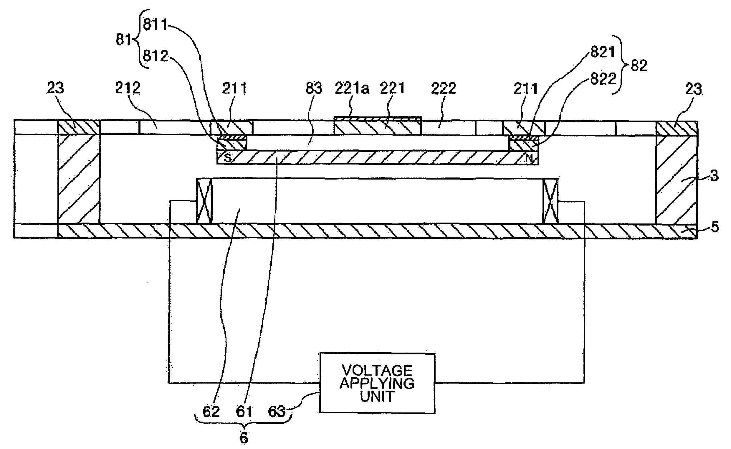
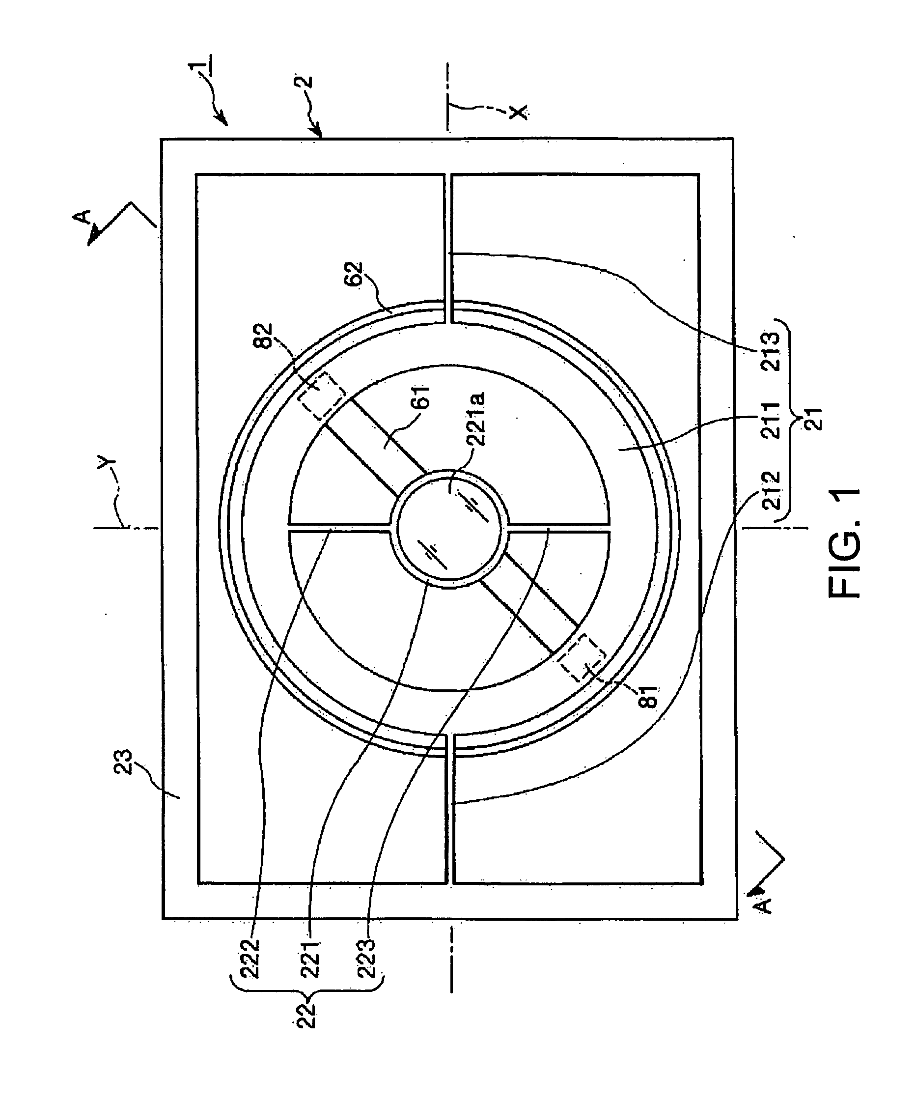
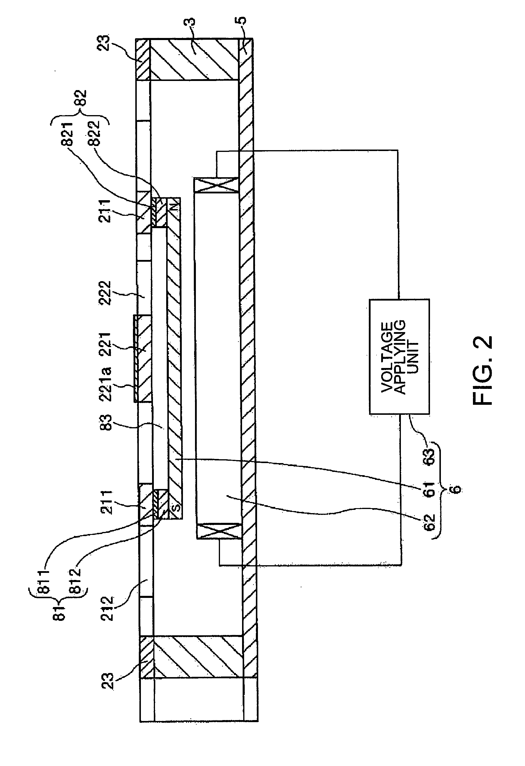
[0048]FIG. 1 is a plan view showing a preferable embodiment of the actuator according to the invention. FIG. 2 is a sectional view along with the line A-A of FIG. 1. FIG. 3 is a block diagram showing a driving unit included in the actuator shown in FIG. 1. FIG. 4A and FIG. 4B respectively show examples of a generated voltage at a first voltage generating portion and a second voltage generating portion. Note that hereinafter for the sake of convenience of explanation the front side of FIG. 1 is called upper side, the rear side thereof is called bottom side, the right side thereof is called right side and the left side thereof is called left side. Further, the upper side of FIG. 2 is called upper side, the bottom side thereof is called bottom side, the right side thereof is called right ...


PUM


Abstract

An actuator includes: a first vibrating system having a frame-like driving member and a pair of first axis members holding the driving member from both sides so that the driving member is rotatable about an X axis; a second vibrating system having a movable plate provided inside the driving member and a pair of second axis members holding the movable plate on the driving members from both sides so that the movable plate is rotatable about a Y axis orthogonal to the X axis; a driving unit including a permanent magnet provided on the driving member, a coil provided to oppose the permanent magnet and a voltage applying unit applying voltage to the coil; and a spacer sandwiched between the driving member and the permanent magnet so as to form space preventing intervention by the movable plate. The permanent magnet is provided such that a line segment connecting both poles of the permanent magnet inclines, in a plan view of the movable plate, with respect to the X axis and the Y axis. The voltage applying unit includes a voltage generating portion generating a first alternating voltage and a second alternating voltage having different frequencies and a voltage superimposing portion superimposing the first voltage and the second voltage. The voltage superimposed at the voltage superimposing portion is applied to the coil so that the movable plate rotates about the X axis with a frequency of the first voltage and about the Y axis with a frequency of the second voltage.

Description

BACKGROUND OF THE INVENTION[0001]1. Technical Field[0002]The present invention relates to an actuator, an optical scanner and an image forming apparatus.[0003]2. Related Art[0004]As an optical scanner used for drawing by utilizing optical scanning in a printer or the like, there is known one performing two-dimensional scanning (see, for example JP-A-08-322227).[0005]The optical scanner disclosed in JP-A-08-322227 has a scanner main body including a frame-like outer movable plate, a pairs of first torsion bars axially supporting the outer movable plate so that the outer movable plate is swingably supported (rotatable) about an X axis, an inner movable plate provided inside the outer movable plate, a pair of second torsion bars axially supporting the inner movable plate so that the inner movable plate is swingable about a Y axis orthogonal to the X axis, a pair of driving coils respectively provided in the outer movable plate and the inner movable plate, and a pair of permanent magnet...

Claims


Application Information

Patent Timeline
Patent Type & Authority Applications(United States)
IPC IPC(8): G02B26/10H02K33/00
CPCH02K33/16G02B26/101G02B26/085
Inventor MIZOGUCHI, YASUSHI
Owner SEIKO EPSON CORP
Why Eureka
Try Eureka