

De-interlacing method and method of compensating a de-interlaced pixel
a deinterlacing and pixel technology, applied in the field of video processing, can solve problems such as the propagation of luminance errors due to recursive references, and achieve the effect of compensating the luminance of a deinterlacing pixel and improving display quality
- Summary
- Abstract
- Description
- Claims
- Application Information
AI Technical Summary
Benefits of technology
Problems solved by technology
Method used
Image

Examples
Embodiment Construction
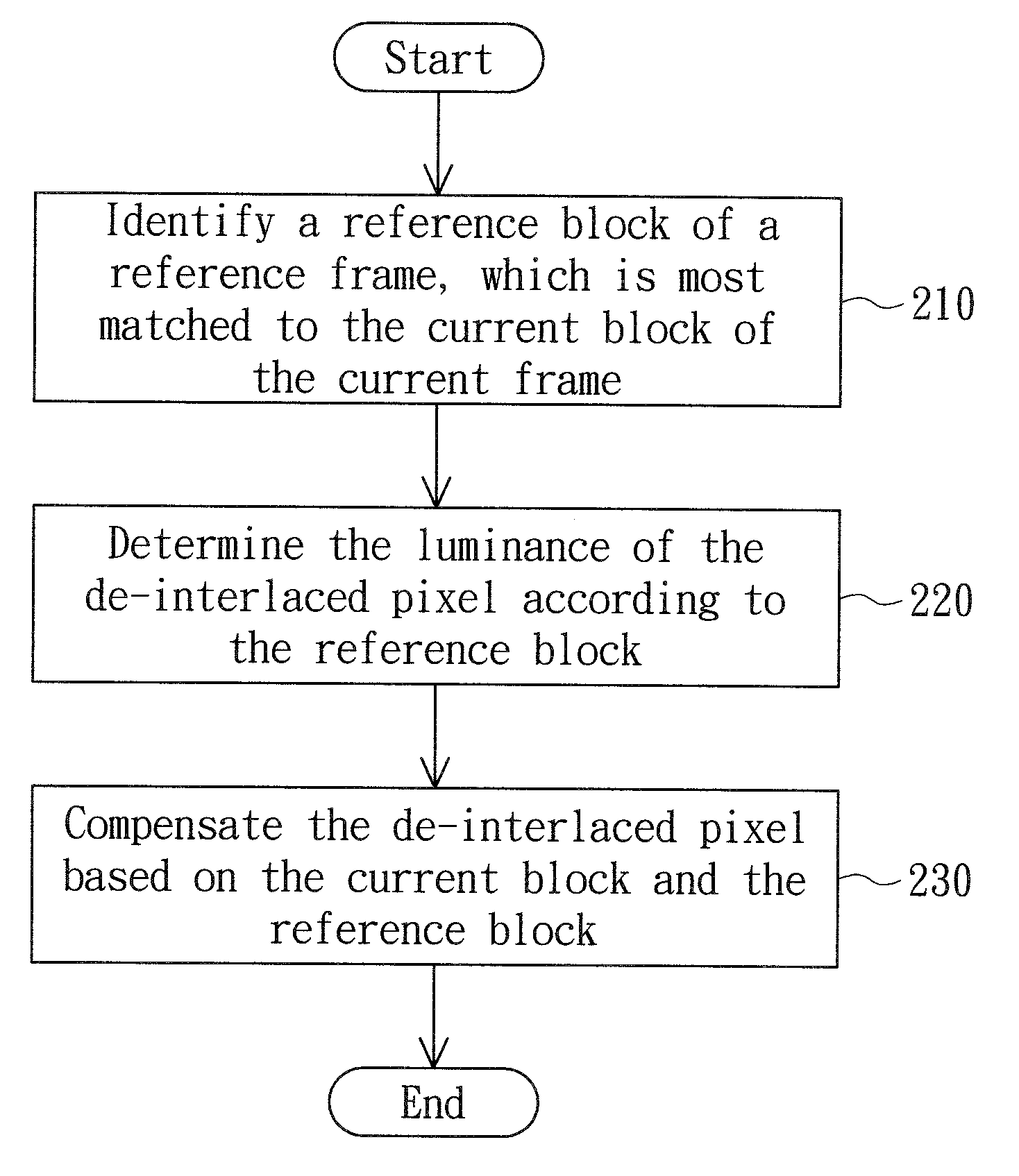
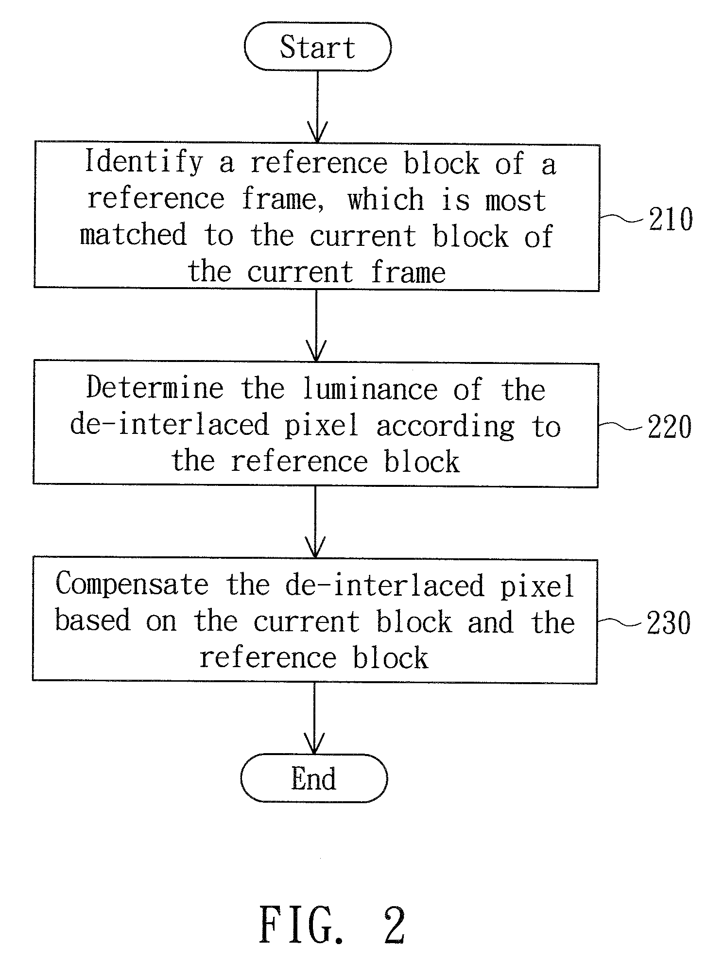
[0014]FIG. 2 shows a flowchart of a motion-compensated de-interlacing method that compensates a de-interlaced pixel according to an embodiment of the present invention. The de-interlacing method in FIG. 2 is exemplified by pixel 121 in FIG. 1.
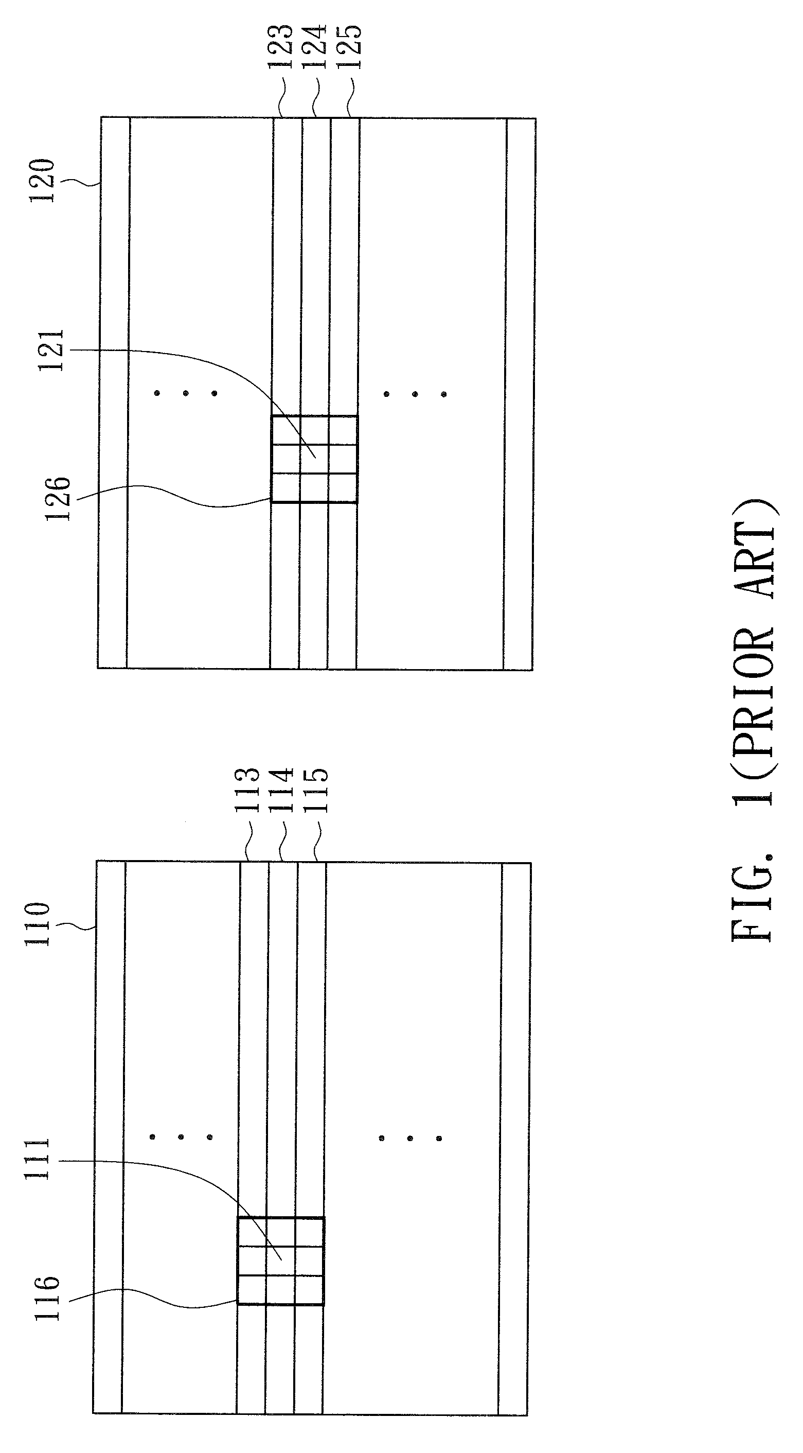
[0015]In step 210, identify a reference block of the reference frame 110, which is determined to be most matched to the current block 126 of the current frame 120, wherein the pixel 121 is positioned in the current block 126. In this embodiment, the reference block 116 is determined to be the matched block.
[0016]Next, in step 220, determined the luminance of the pixel 121 in the current block 126 of the current frame 120 based on the reference block 116 of the reference frame 110. In this embodiment, the pixel 121 corresponds to the reference pixel 111 in the reference block 116 and the luminance of the pixel 121 is determined to be the luminance of the reference pixel 111, such as Ld.
[0017]Afterwards, in step 230, compensate the luminance Ld o...
PUM
 Abstract
Description
Claims
Application Information