Backlight module

a backlight module and backlight technology, applied in lighting support devices, lighting and heating apparatus, instruments, etc., can solve the problems of space utilization and power consumption, enlarged size, and prior art increase the length of lamps, so as to improve the irradiance of the backlight module, minimize the volume of the liquid crystal display, and improve the brightness at the two corners

Inactive Publication Date: 2006-06-06
INNOLUX CORP
View PDF9 Cites 4 Cited by
  • Summary
  • Abstract
  • Description
  • Claims
  • Application Information

AI Technical Summary

Benefits of technology

[0014]To enhance the irradiance of the backlight module, a diffusion sheet and a prism sheet are further incorporated. The diffusion sheet is disposed on the top surface of the light guide plate, and the prism sheet is disposed on the diffusion sheet. A framer is used to integrate the light guide plate, the light source, the reflection mask and the light compensator into a single unit.
[0015]According to the above, the present invention installs a light compensator in the reflection mask or forms multiple reflection surfaces directly on the reflection mask, such that the brightness at the two corners of the light guide plate near the two ends of the light source is enhanced. The light guide plate can thus provide a uniform plane light source, while the minimized volume of the liquid crystal display is maintained.

Problems solved by technology

However, the environment of operating desktop terminal / monitors and the trend of power saving with environment protection in mind have manifested the problems of cathode ray tube in terms of space utilization and power consumption.
To overcome the problem, prior art increases the length of the lamp, such that the regions with insufficient brightness extend externally to the light guide plate.
However, the width of the liquid crystal display is consequently increased resulting in an enlarged size.

Method used


Image

  • Backlight module
  • Backlight module
  • Backlight module

Examples


first embodiment

[0022

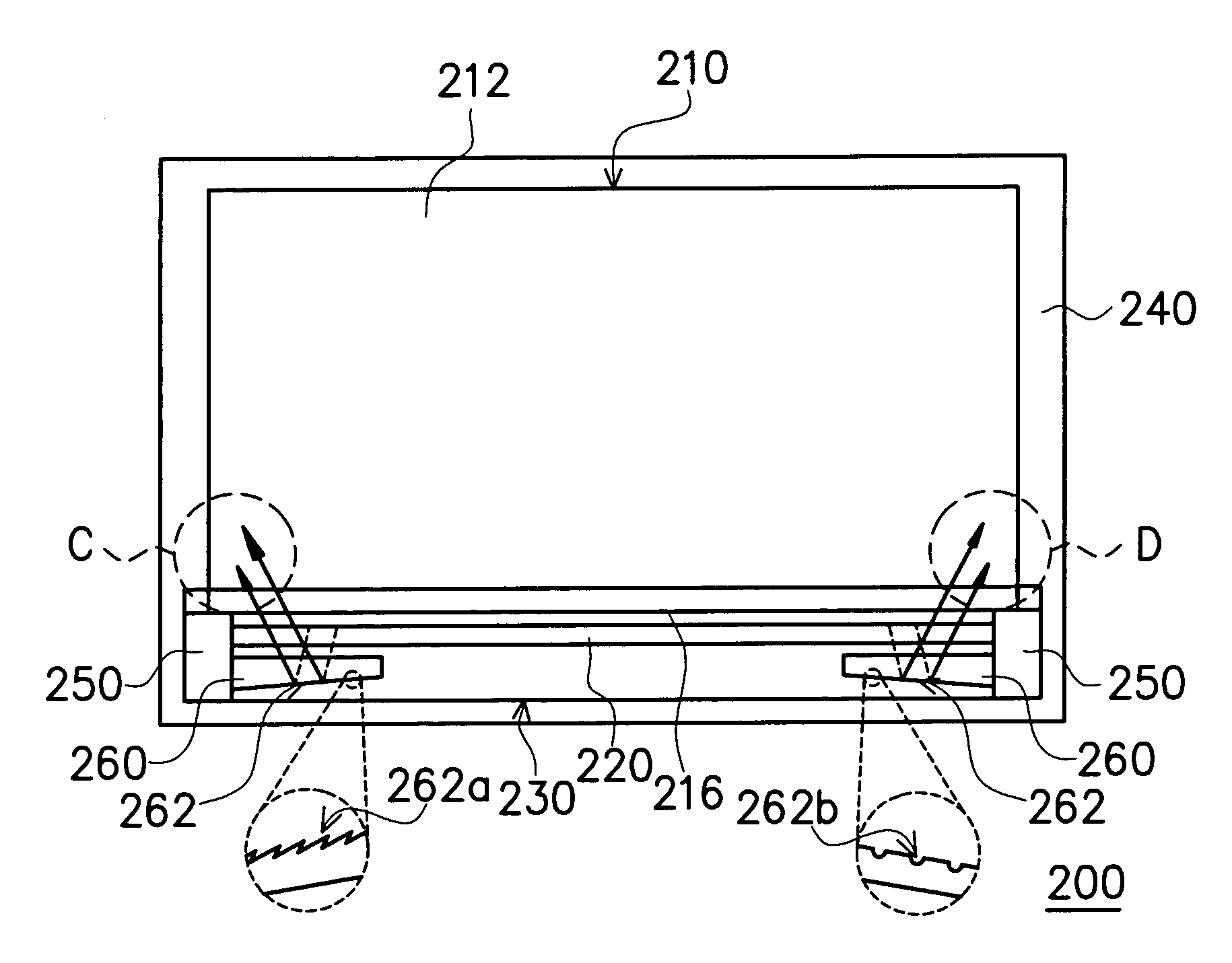
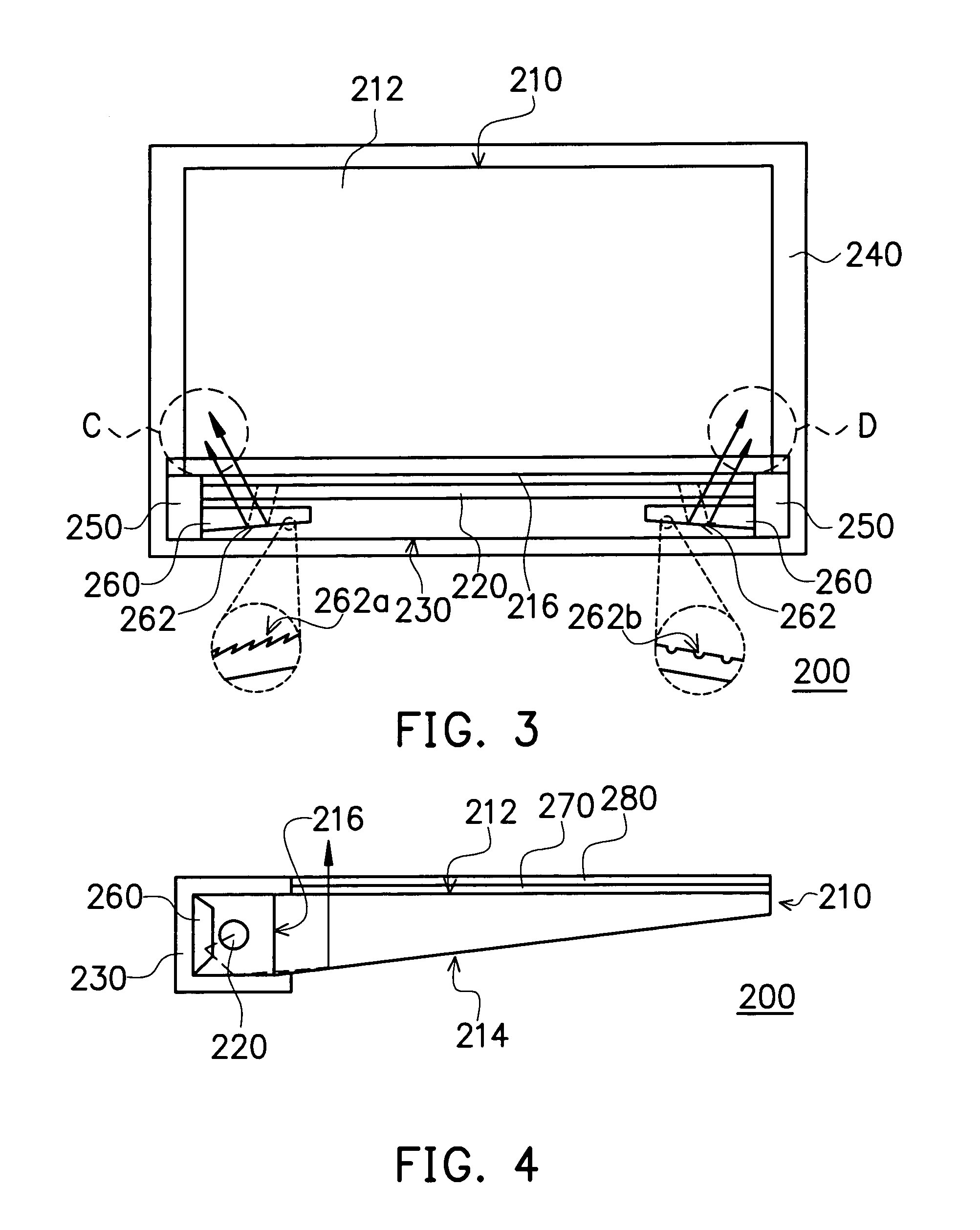
[0023]FIG. 3 shows a top view of a backlight module provided in the first embodiment, and FIG. 4 shows a side view of the backlight module. Referring to FIGS. 3 and 4, the backlight module 200 comprises a light guide plate 210, a light source 220, a reflection mask 230, a frame 240 and a light compensator 260. The light guide plate 210 is wedge-shaped preferably. For example, The light guide plate 210 has a top surface 212, a bottom surface 214 and a side surface 216. The top surface 212 is designed as a projecting plane, the bottom surface 214 is designed as a reflection plane, and the side surface 216 is designed as an incident plane. The bottom surface 214 includes a step surface or multiple recesses thereon, such that the light incident thereon is scattered and / or reflected.

[0024]The light source 220 includes a cold cathode fluorescent lamp, for example. The light source 220 is disposed next to the side surface 216 with the two ends fixed on a lamp holder 250. The light pro...

second embodiment

[0029

[0030]FIG. 5 shows the backlight module provided in a second embodiment of the present invention. Referring to FIG. 5, the overall structure of the backlight module 300 is similar to that provided in the first embodiment. The backlight module 300 differs from the backlight module200 by forming a plurality of reflection planes 332 directly on the reflection mask 330. The reflection planes 332 face the two ends of the light source 320 with stepped surfaces or multiple recesses to scatter the incoming light provided by the light source. The brightness at the two comers of the light guide plate 310 (regions E and F) near the two ends of the light source 320 is thereby compensated.

[0031]According to the above, the present invention has at least the following advantages.

[0032]1. The backlight module compensates the brightness at the two comers of the light guide plate near the two ends of the light source, such that the top surface of the light guide plate provides a uniform plane li...


PUM


Abstract

A backlight module, suitable for supplying a plane light source. The backlight module has a light guide plate, a reflection mask and a light compensator. The light source is disposed next to a side surface of the light guide plate, such that the light generated thereby is incident on the side surface of the light guide plate, transmitted through the bottom surface, and projecting from the top surface of the light guide plate. The reflection mask is disposed next to the sidewall of the light guide plate to cover the light source. The light compensator is disposed in the reflection mask. By disposing the light compensator with multiple reflection planes in the reflection mask or forming multiple reflection surfaces of the reflection mask, the brightness at the two comers of the light guide plate near the two sides of the light source can be compensated.

Description

CROSS-REFERENCE TO RELATED APPLICATION[0001]This application claims the priority benefit of Taiwan application serial no. 92200124, filed on Jan. 6, 2003.BACKGROUND OF THE INVENTION[0002]1. Field of the Invention[0003]The invention relates in general to a backlight module, and more particularly, to a backlight module that effectively compensates brightness at two corners of a light guide plate near two sides of a light source.[0004]2. Related Art of the Invention[0005]The advancement of multi-media has benefited from the forward looking progress of semiconductor technique or human-machine interface display. For the .display, cathode ray tube (CRT) has dominated the markets for years due to its outstanding display quality and economics. However, the environment of operating desktop terminal / monitors and the trend of power saving with environment protection in mind have manifested the problems of cathode ray tube in terms of space utilization and power consumption. Therefore, the liqu...

Claims


Application Information

Patent Timeline
Patent Type & Authority Patents(United States)
IPC IPC(8): F21V7/04F21V8/00G02B6/00
CPCG02B6/0013G02B6/0031G02B6/0046G02B6/0038
Inventor MAI, CHE-KUEI
Owner INNOLUX CORP
Why Eureka
Try Eureka