
LED (Light Emitting Diode) lamp shade

A technology of LED lamps and LED lamps, applied in the field of lighting, can solve the problems of low illumination, no LED light source, insufficient illumination uniformity, etc., and achieve the effect of improving illumination and uniform light color temperature difference

Inactive Publication Date: 2014-02-12
东莞市博阳光电科技有限公司
View PDF0 Cites 1 Cited by
  • Summary
  • Abstract
  • Description
  • Claims
  • Application Information

AI Technical Summary

Problems solved by technology

[0003] The existing LED lamps have the characteristics of saving electricity and long service life, but due to the influence of the luminous characteristics of LED light sources, such as low irradiance and insufficient uniformity of illumination, etc., when they are actually applied to LED lamps, the lampshade must be used for secondary lighting. Secondary light distribution, but most of the LED lamp shades used as secondary light distribution in the existing market only focus on protecting the light source, and there is no LED light source to make a more efficient light distribution design, but because of the generally spherical design, resulting in light distribution not effectively

Method used


Image

  • LED (Light Emitting Diode) lamp shade
  • LED (Light Emitting Diode) lamp shade
  • LED (Light Emitting Diode) lamp shade

Examples


Embodiment 1

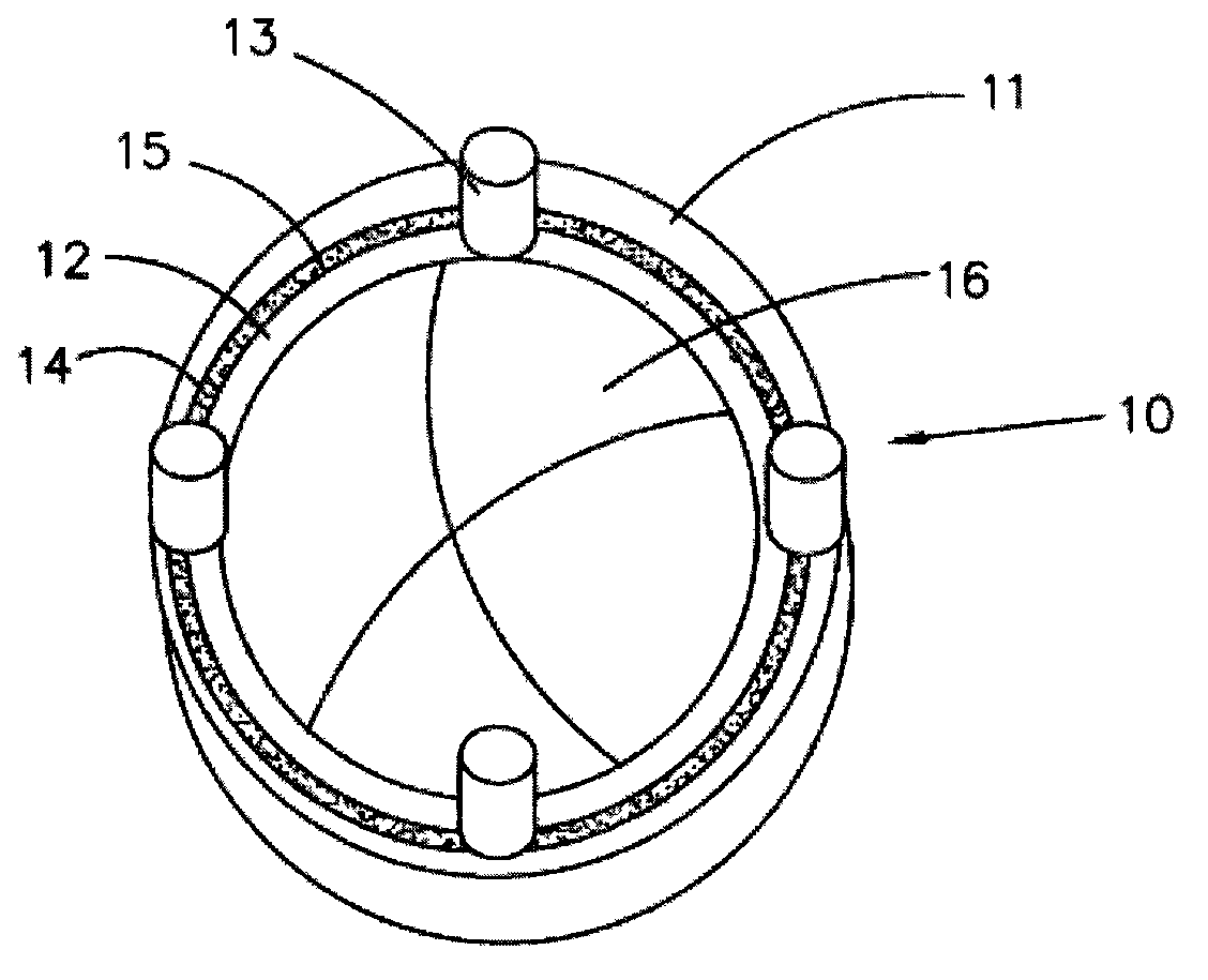
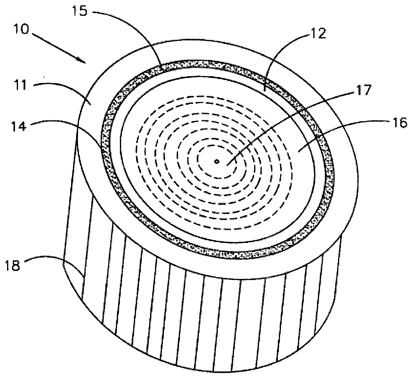
[0021] Both the outer lens 11 and the inner lens 12 are in a hemispherical structure, the connecting portion 13 is in a cylindrical structure, and the ends of the outer lens 11 and the inner lens 12 are fixedly connected by the connecting portions 13 arranged at intervals.

Embodiment 2

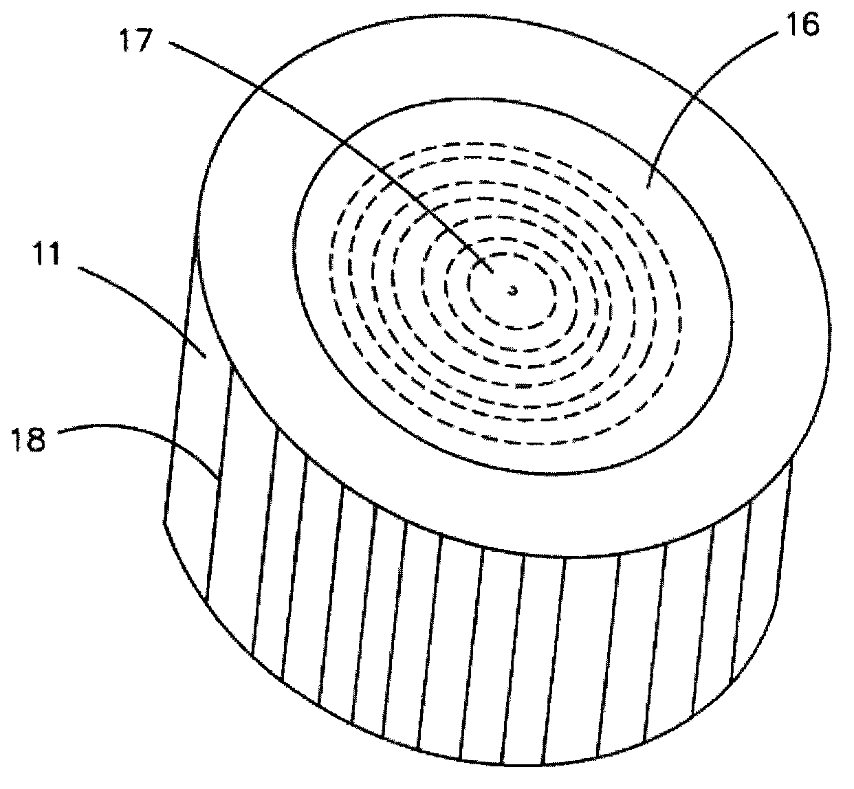
[0023] Both the outer lens 11 and the inner lens 12 are of cylindrical structure, the connecting portion 13 is integrally formed with the bottom end of the outer lens 11 and the bottom end of the inner lens 12, and the inner lens 12 is contained in the receiving space 16 An optical refraction part 17 is integrally formed, and the optical refraction part 17 is a concave lens structure, and the LED light source is accommodated on one side of the optical refraction part 17; the outer lens 11 is provided with a stripe part 18, so that the LED The light emitted by the light source becomes softer.

[0024] The present invention adopts the following method to manufacture and form: first, the outer lens 11 and the inner lens 12 are molded, and the inner side wall of the outer lens 11 and the outer side wall of the inner lens 12 are coated with a binding agent of a thermosetting material, and then a certain amount is added in the glue injection machine. Proportioning the mixture of pho...


PUM


Abstract

The invention discloses an LED (Light Emitting Diode) lamp shade, which is used in an LED lamp. The LED lamp comprises an LED lamp body and an LED light source. The LED lamp shade is arranged on the LED lamp body. The LED lamp shade comprises a shade body. The shade body comprises an outer lens and an inner lens which are arranged at interval. A connecting part is arranged between the end part of the outer lens and the end part of the inner lens. A containing groove is formed between the outer lens and the inner lens. A fluorescent adhesive layer is arranged in the containing groove. A holding space is concavely arranged in the inner lens. The LED lamp shade disclosed by the invention has the advantages that since the containing groove is formed between the inner lens and the outer lens in a surrounding way and the fluorescent adhesive layer is arranged in the containing groove, according to an optical effect of the inner lens and the outer lens, light emitted by the LED light source can be controlled within a certain angle range, the illumination intensity of the LED light source is improved, and the color temperature difference of the light emitted by the LED light source is enabled to be uniform.

Description

technical field [0001] The invention relates to the technical field of illumination, in particular to an LED lamp shade. Background technique [0002] LED (Light Emitting Diode), its basic structure is an electroluminescent semiconductor material. Based on the characteristics of LED light source such as small size, low power consumption, long service life, and high brightness, LED will be the most ideal light source to replace traditional light sources. With the maturity of LED technology, LED lamps designed with LED light sources have been widely used. [0003] The existing LED lamps have the characteristics of saving electricity and long service life, but due to the influence of the luminous characteristics of LED light sources, such as low irradiance and insufficient uniformity of illumination, etc., when they are actually applied to LED lamps, the lampshade must be used for secondary lighting. Secondary light distribution, but most of the LED lamp shades used as second...

Claims


Application Information

Patent Timeline
Patent Type & Authority Applications(China)
IPC IPC(8): F21V3/04F21V5/04F21V9/00F21Y101/02F21V9/16F21Y115/10
Inventor 胥海洋
Owner 东莞市博阳光电科技有限公司
Learn More