Light source with photoluminescence emitter

a light source and photoluminescence technology, applied in the field of light sources, can solve the problems of poor color rendering index, no red converter known which provides all the good properties of cerium-doped yag, and poor efficiency of the light-emitting diode assembly, and achieves improved color rendering index, high efficiency, and high luminance

Pending Publication Date: 2021-01-07
SCHOTT AG
View PDF7 Cites 2 Cited by
  • Summary
  • Abstract
  • Description
  • Claims
  • Application Information

AI Technical Summary

Benefits of technology

[0010]Therefore, the object of the invention is to provide a light source exhibiting high luminance and high efficiency, which emits red light or light that contains r

Problems solved by technology

The most prominent light converter is cerium-doped YAG (Ce:YAG; YAG—yttrium aluminum garnet) which, however, due to its emission spectrum with a small red fraction, only provides for a poor color rendering index.
However, there is no red converter known which provides all the good properties of the cerium-doped YAG in terms of efficiency, performance stability, thermal stability, blue absorption, and price.
However, when this phosphor is used for white light LEDs, the problem arising is that only a small fraction of the light emitted by the blue LED is absorbed, so that such a light-emi

Method used


Image

  • Light source with photoluminescence emitter
  • Light source with photoluminescence emitter
  • Light source with photoluminescence emitter

Examples


Embodiment Construction

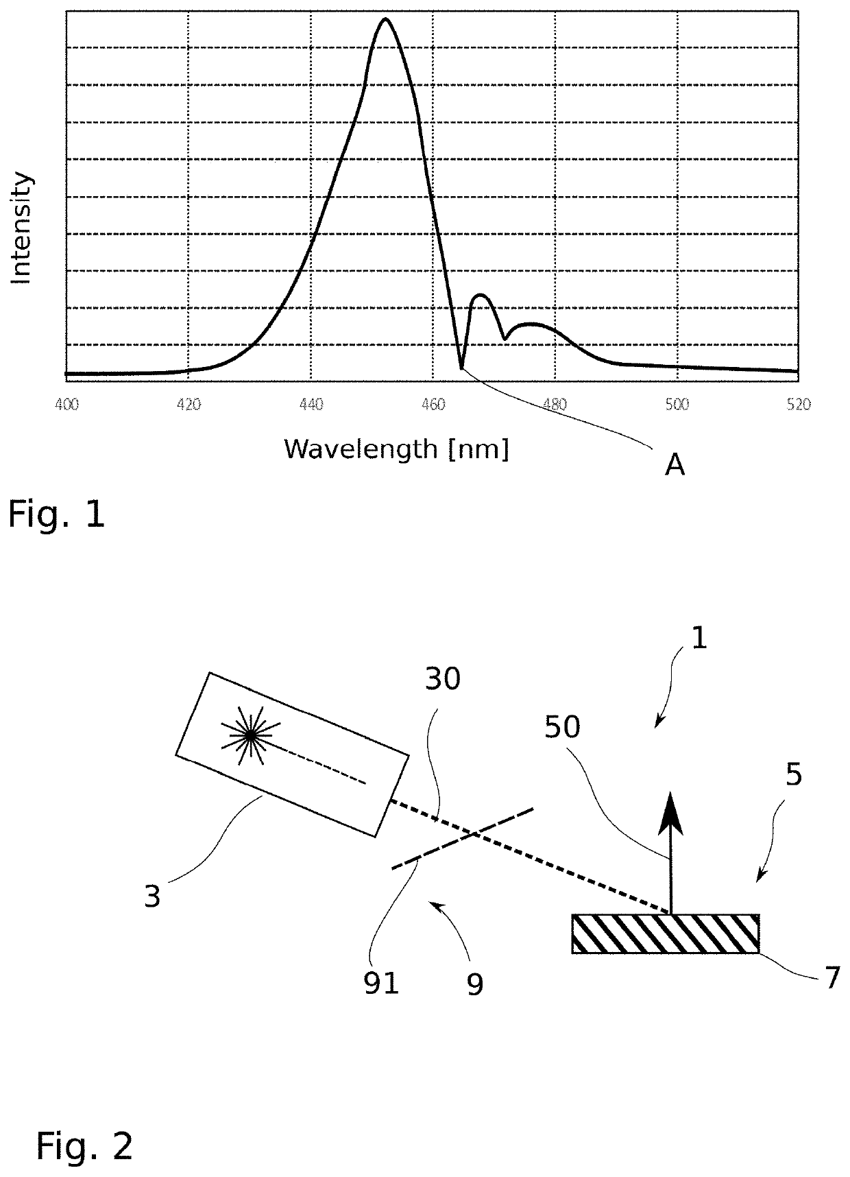
[0035]FIG. 1 schematically shows the spectrum of diffuse reflection of an Eu3+-doped ceramic converter that is excited by a blue light-emitting diode. The illustrated part of the spectrum is in the blue spectral range and essentially includes the blue excitation light of the light-emitting diode, which is scattered back at the converter. The spectrum of the light-emitting diode is represented as a broad peak in the spectrum. The narrow dip at about 465 nm, marked “A”, which can be seen in the spectrum of FIG. 1 and which almost reaches the ground level, reveals that for the absorption line at 465 nm absorption is 90% or more of the irradiated power. Thus, in principle, absorption of blue light is not bad in an Eu3+-doped material. Rather, the graph shows that the narrow absorption band of the Eu3+ ions, when compared to the rather broad spectrum of the LED, implies only low total absorption of the LED light and hence poorly effective photoluminescence excitation and thus results in ...


PUM


Abstract

A light source is provided that includes a laser operable to emit laser light at a wavelength in a range from 460 nanometers to 470 nanometers and a converter assembly arranged so as to absorb the laser light emitted by the laser and to emit photoluminescent light produced by the laser light and having a longer wavelength than the laser light. The converter assembly has a converter element with a ceramic doped with Eu3+ such that under irradiation of the laser light the converter assembly emits photoluminescent light in the red spectral range.

Description

CROSS REFERENCE TO RELATED APPLICATIONS[0001]This application claims benefit under 35 USC § 119 of German Application No. 10 2019 118 060.0, filed Jul. 4, 2019, the entire contents of which are incorporated herein by reference.BACKGROUND1. Field of the Invention[0002]The invention generally relates to light sources that generate light through photoluminescence.2. Description of Related Art[0003]Modern LED-based light sources (i.a. white light sources) are based on blue emitting light-emitting diodes, the light of which is partly converted into yellow light using photoluminescence converters. Photoluminescence converters are also known as phosphors, light converters, fluorescence converters, or simply converters. The combination of the yellow light with the rest of the blue light creates a white light impression. The most prominent light converter is cerium-doped YAG (Ce:YAG; YAG—yttrium aluminum garnet) which, however, due to its emission spectrum with a small red fraction, only pro...

Claims


Application Information

Patent Timeline
IPC IPC(8): G03B21/20G03B21/16G03B33/12C09K11/77
CPCG03B21/204C09K11/7794G03B33/12G03B21/16F21V9/30F21V29/50C09K11/681
Inventor HAGEMANN, VOLKERSEIDL, ALBRECHT
Owner SCHOTT AG
Why Eureka
Try Eureka