Planar light source

a light source and planar technology, applied in the field of planar light sources, can solve the problems of increased backlight module cost, inferior uniformity of planar light source emitting from light-guided plates, and high price of light-guided plates and optical films, and achieve the effect of large size and uniform brightness

Inactive Publication Date: 2006-06-01
DELTA ELECTRONICS INC
View PDF0 Cites 3 Cited by
  • Summary
  • Abstract
  • Description
  • Claims
  • Application Information

AI Technical Summary

Benefits of technology

[0031] According to the present invention, a portion of the light emitting from the CCFFL is reflected by the transflective film and the reflective component and is emitted through the transflective film disposed over the reflective component. Conseuqently, the brightness of the light-emitting surface over a non-emitting area is compensated. In conclusion, the present invention employs the design of the transflective film and the reflective components to compensate the brightness over the non-emitting area so that a planar source with a large size and uniform brightness can be obtained by the way of assembling a plurality of CCFFLs.

Problems solved by technology

However, since the lamp is disposed at the side of the light-guided plate, the uniformity of the planar light source emitting from the light-guided plate is thus inferior.
Thus, the cost of the backlight module is raised because the prices of the light-guided plate and the optical films are expensive.
Hence, from the above description, an assembling process of the backlight module is complicated, and the assembling cost can be further raised.
In general, the manufacturing of a larger size CCFFL is difficult.
Further, the problems of high manufacturing cost and low yield will be encountered when the CCFFL is applied in the large size display devices or illuminating devices.

Method used


Image

  • Planar light source
  • Planar light source
  • Planar light source

Examples


first embodiment

The First Embodiment

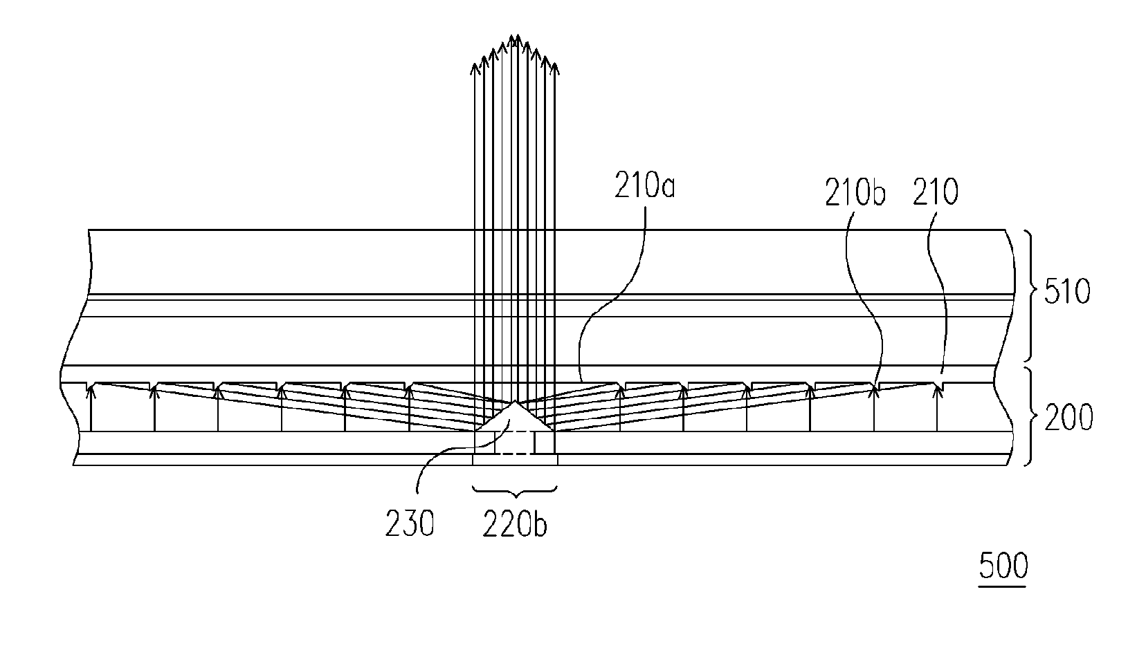
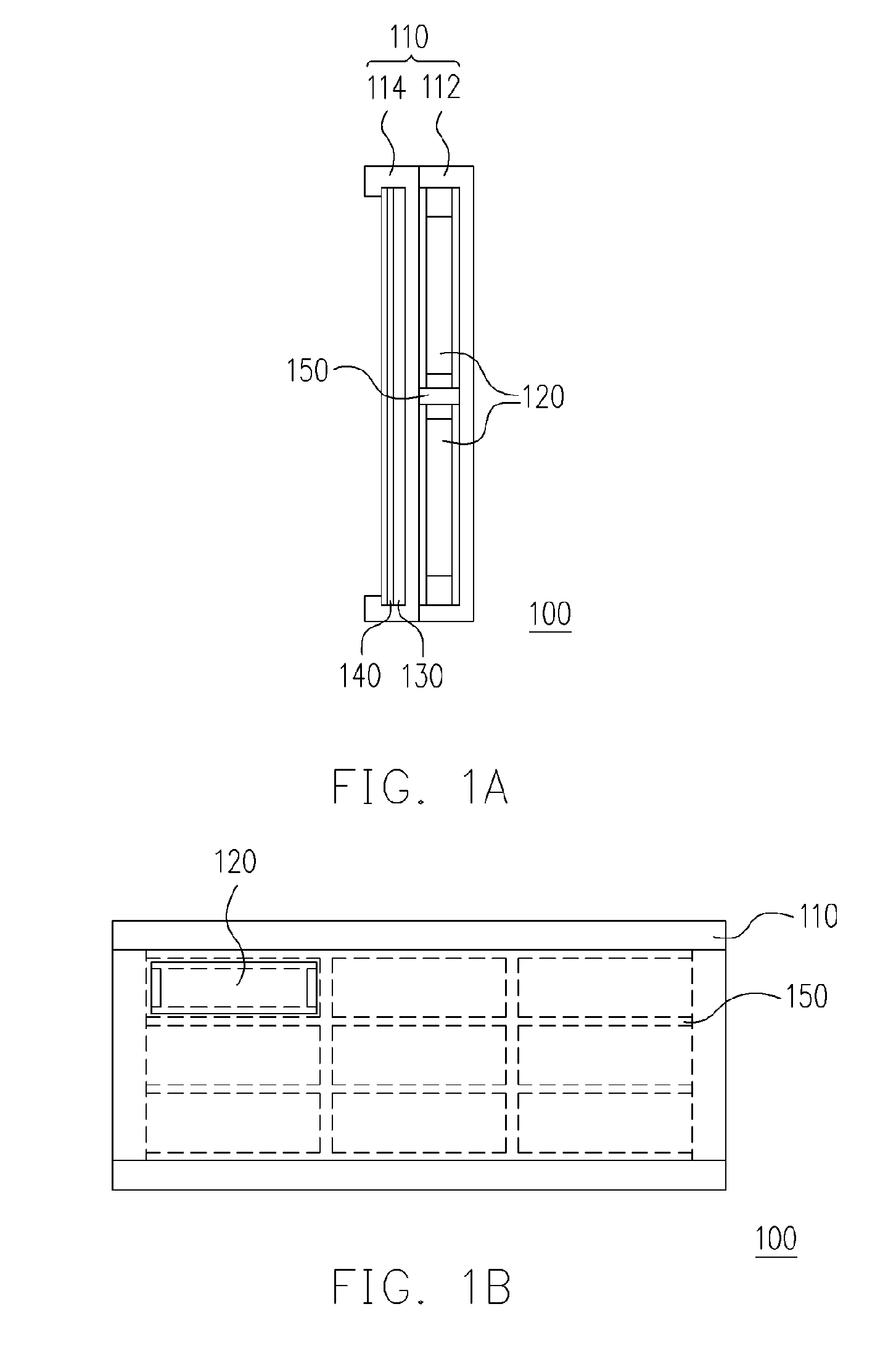
[0042]FIG. 1A is a cross sectional side view of a planar light source of the first embodiment, according to the present invention. Referring to FIG. 1, a planar light source 100 of the embodiment comprises, for example, an outer frame 110, a plurality of cold cathode flat fluorescent lamps (CCFFLs) 120, a diffuser plate 130 and at least one optical film plate 140. The outer frame 110 is constructed with a light source frame 112 and an optical film frame 114. The diffuser plate 130 and other optical film plates 140 are assembled into the optical film frame 114 disposed on a light-emitting surface of the light source frame 112. Furthermore, the diffuser plate 130 is disposed between the optical film plates 140 and the CCFFLs 120. In the embodiment, the optical film plates 140 may be, for example, a diffuser film plate and a prism film plate.

[0043]FIG. 1B is a diagram illustrating the arrangement of the CCFFLs according to the first embodiment of the present invent...

second embodiment

The Second Embodiment

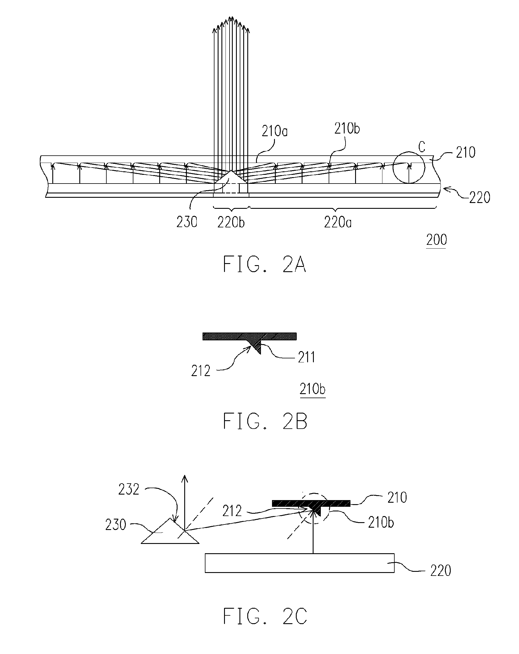
[0051]FIG. 3 is a cross sectional view of a planar source according to the second embodiment of the present invention. Referring to FIG. 3, a planar source 300 of the embodiment comprises a transflective film 310, a plurality of CCFFLs 320 and at least one reflective component 330. The planar light source 300 of this embodiment is similar to the planar light source 200 of the first embodiment except that the reflective films 310 employed by this embodiment are not designed to have the transflective surface 212 (as shown in FIG. 2B and FIG. 2C). A portion of the light emitting from the CCFFLs 320 of the embodiment can be reflected between the CCFFLs 320 and the transflective film 310 by using the transflective film constructed with an approximately chosen material. Finally, the reflected light is again reflected by the reflective components 330 and is emitted through the transflective film 310 disposed over the reflective component 330 to achieve the purpose of b...

third embodiment

The Third Embodiment

[0054]FIG. 5 is a cross sectional view of a planar light source according to of the third embodiment the present invention. Referring to FIG. 5, the planar light source 400 of this embodiment is similar to the planar light source 300 of the second embodiment, except that the reflective component 430 of the planar light source 400 of the embodiment is disposed between each CCFFL and at the same level as the CCFFLs.

[0055] In this embodiment, the reflective component may efficiently employ the light emitting from the fringes of the CCFLs to compensate the light brightness over the reflective components 430.


PUM

PropertyMeasurementUnit
areaaaaaaaaaaa
fluorescentaaaaaaaaaa
thermal dissipationaaaaaaaaaa

Abstract

A planar light source including a transflective film, a plurality of cold cathode fluorescence flat lamps and at least one reflective component to provide a uniform light source is described. A portion of the light emitted from the emitting areas of the cold cathode fluorescence flat lamps passes through the transflective film, and the other portion of the light is reflected to the reflective component by the transflective film. Then, the light is reflected to the dark areas between the emitting areas to compensate the brightness of the dark areas. When the brightness of the dark areas is compensated, the planar light source provides a uniform light without dark stripes.

Description

CROSS-REFERENCE TO RELATED APPLICATION [0001] This application claims the priority benefit of Taiwan application serial no. 93136433, filed Nov. 26, 2004. BACKGROUND OF THE INVENTION [0002] 1. Field of the Invention [0003] The present invention generally relates to a planar light source. More particularly, the present invention relates to a planar light source composed of a plurality of cold cathode flat fluorescent lamps (CCFFLs). [0004] 2. Description of Related Art [0005] Along with the advancement of the industry, mobile phones, digital cameras, digital video cameras, notebooks, desktop computers and other digitized tools, etc, are all being developed to be more convenient, more functional and to have appealing appearances. The display screens of the mobile phone, the digital camera, the digital video camera, the notebook and the desktop computer are an indispensable communicating interface between the user and the machine, which allows the user to operate these products more co...

Claims


Application Information

Patent Timeline
Patent Type & Authority Applications(United States)
IPC IPC(8): G02F1/1335
CPCG02B6/0038G02B6/0068G02B6/0078G02F1/133555G02F1/133604G02F1/133606G02F2001/133607G02F1/133607
Inventor LIU, YU-CHIWU, WEN-CHILIU, YUAN-WENPAN, KUNG-TUNGFRAN, YUI-SHIN
Owner DELTA ELECTRONICS INC
Why Eureka
Try Eureka