Motion Measuring Device, Motion Measuring System, In-Vehicle Device, Motion Measuring Method, Motion Measurement Program, and Computer-Readable Storage

a technology of motion measurement and in-vehicle device, which is applied in the field of motion measurement system, in-vehicle device, motion measurement method, and computer-readable storage medium, can solve the problems of cumbersome calibration of the physical relationship between the two lenses, decreased motion measurement accuracy, and low cost, and achieves the effect of small space and low cos

Inactive Publication Date: 2008-09-11
NARA INSTITUTE OF SCIENCE AND TECHNOLOGY
View PDF5 Cites 59 Cited by
  • Summary
  • Abstract
  • Description
  • Claims
  • Application Information

AI Technical Summary

Benefits of technology

[0031]According to the above-arranged motion measuring method, since the processes in the first to fifth steps are similar to the processes performed by the motion measuring device of the present invention, it is possible to obtain effects similar to the effect of the motion measuring device of the present invention.
[0032]According to the motion measuring device of the present invention, since the three-dime...

Problems solved by technology

First, by using the simplified model of the capturing object in the technique of obtaining motion of the capturing object with the use of a monocular camera, motion measurement accuracy decreases. Similarly, even when the camera model is simplified, motion measurement accuracy decreases.
Secondly, in the technique of obtaining motion of the capturing object with the use of a ste...

Method used


Image

  • Motion Measuring Device, Motion Measuring System, In-Vehicle Device, Motion Measuring Method, Motion Measurement Program, and Computer-Readable Storage
  • Motion Measuring Device, Motion Measuring System, In-Vehicle Device, Motion Measuring Method, Motion Measurement Program, and Computer-Readable Storage
  • Motion Measuring Device, Motion Measuring System, In-Vehicle Device, Motion Measuring Method, Motion Measurement Program, and Computer-Readable Storage

Examples


Embodiment Construction

[0048][1. Device Configuration Outline]

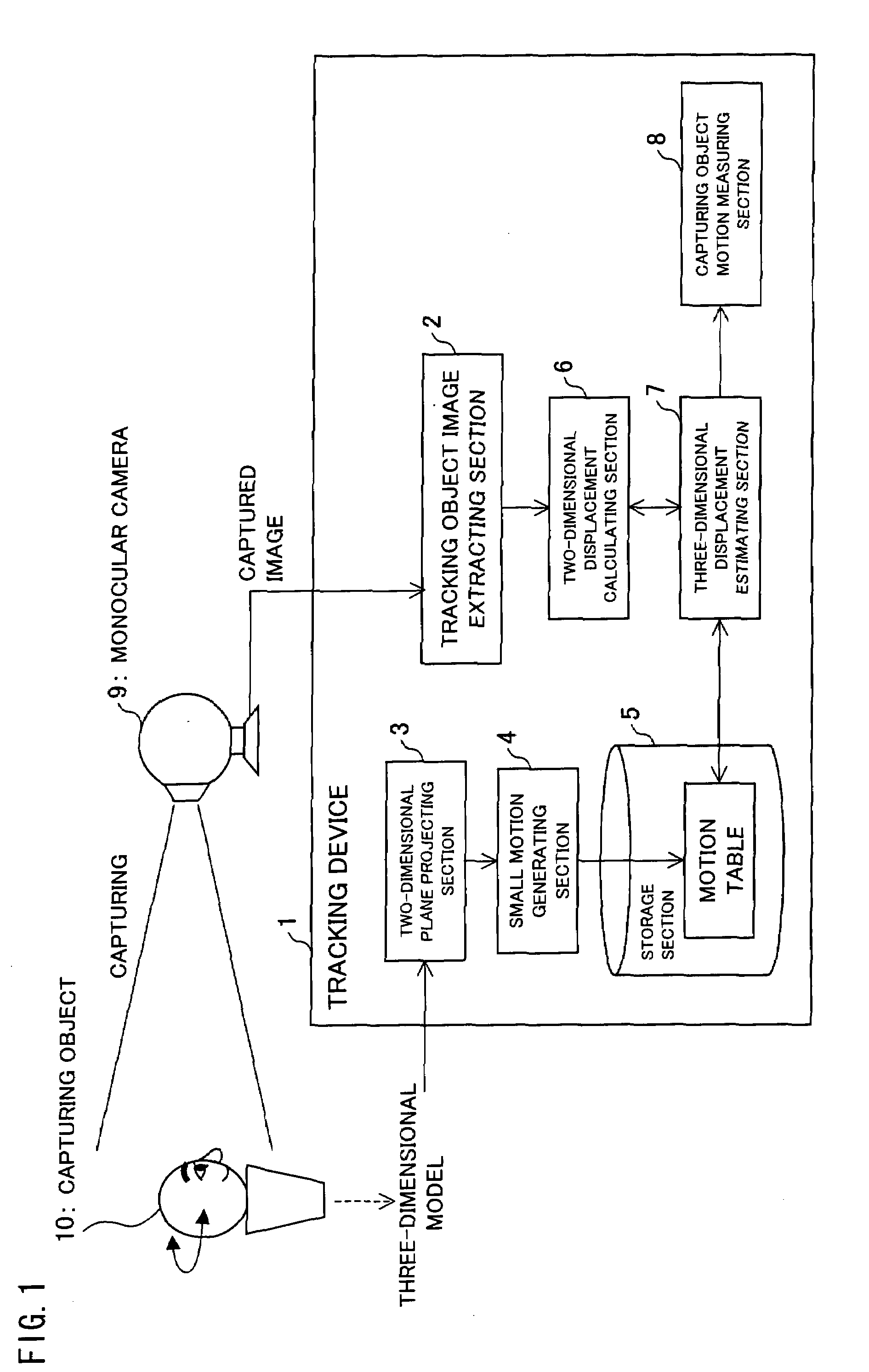
[0049]First of all, the configuration of a tracking device (motion measuring device) according to an embodiment of the present invention will be described with reference to FIG. 1. As illustrated in FIG. 1, the tracking device 1 of the present embodiment includes a tracking object image extracting section (tracking object image extracting means) 2, a two-dimensional plane projecting section (two-dimensional plane projecting means) 3, a small motion generating section (estimated movement amount calculating means) 4, a storage section 5, a two-dimensional displacement calculating section (actual movement amount calculating means) 6, a three-dimensional displacement estimating section (three-dimensional displacement estimating means) 7, and a capturing object motion measuring section 8.

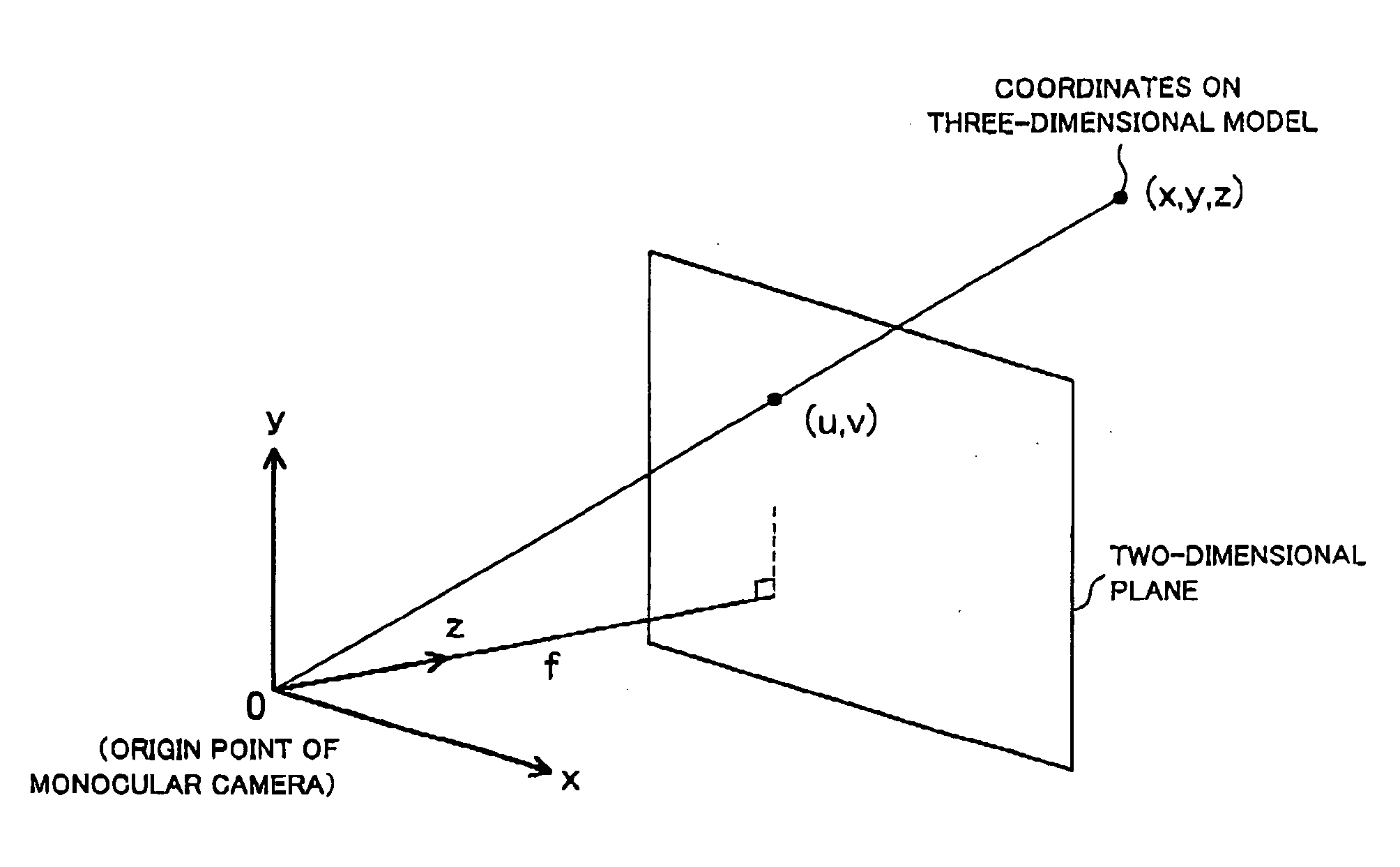
[0050]The tracking object image extracting section 2 extracts, from a motion image (captured image) of a capturing object 10 which has been captured by a monocular ...


PUM


Abstract

An embodiment of the present invention includes: a tracking object image extracting section that extracts a tracking object image, which represents a tracking object, from an image captured by a monocular camera; a two-dimensional displacement calculating section that calculates, as actual movement amounts, amounts of inter-frame movement of the tracking object image; a two-dimensional plane projecting section that generates on a two-dimensional plane a projected image of a three-dimensional model, which represents in three dimensions a capturing object captured by the monocular camera; a small motion generating section that calculates, as estimated movement amounts, amounts of inter-frame movement of the projected image; and a three-dimensional displacement estimating section that estimates amounts of three-dimensional motion of the tracking object on the basis of the actual movement amounts and the estimated movement amounts.

Description

TECHNICAL FIELD[0001]The present invention relates to a motion measuring device, a motion measuring system, an in-vehicle device, a motion measuring method, a motion measurement program, and a computer readable storage medium, for tracking motion of a capturing object captured by a camera.BACKGROUND ART[0002]Conventionally, in order to obtain quantitative motion of a capturing object on the basis of an image (captured image) of a human face or others captured by a monocular camera, a simplified model representing the capturing object was hypothetically generated to obtain motion of the model from motion on the captured image.[0003]For example, to obtain quantitative motion of a human face from a captured image of the human face, models as illustrated in FIG. 7 were used, which are a model representing a human face in planar form (see Non-patent document 1), a model representing a human face in cylindrical form (see Non-patent document 2), and a model representing a human face in ell...

Claims


Application Information

Patent Timeline
IPC IPC(8): G06K9/00
CPCG06T2207/30201G06T7/2046G06T7/251
Inventor MATSUMOTO, YOSHIO
Owner NARA INSTITUTE OF SCIENCE AND TECHNOLOGY
Why Eureka
Try Eureka