Magnetic drive vane pump

a vane pump and magnetic drive technology, applied in the direction of machines/engines, liquid fuel engines, positive displacement liquid engines, etc., can solve problems such as unintended fluid lead

Inactive Publication Date: 2008-09-11
MATSUSHITA ELECTRIC WORKS LTD
View PDF12 Cites 8 Cited by
  • Summary
  • Abstract
  • Description
  • Claims
  • Application Information

AI Technical Summary

Benefits of technology

[0004]Preferably, the rotor magnet is disposed radially outwardly of the stator magnet so that the stator magnet can be arranged within a radial dimension of the stator, which assures to give a compact structure to the pump with respect to the radial direction.
[0006]Further, the rotor magnet is preferred to be fitted around a shaft extending axially from a center of the casing with a vibration absorbing member interposed therebetween. The vibration absorbing member can well absorb radial vibrations possibly caused by an eccentric rotary motion of the rotor, thereby assuring a smooth and silent rotary motion.

Problems solved by technology

However, as the shaft is a constantly moving part, there is always a problem that the sealing may become deteriorated during an extended period of use to result in an unintended lead of the fluid.

Method used


Image

  • Magnetic drive vane pump
  • Magnetic drive vane pump
  • Magnetic drive vane pump

Examples


Embodiment Construction

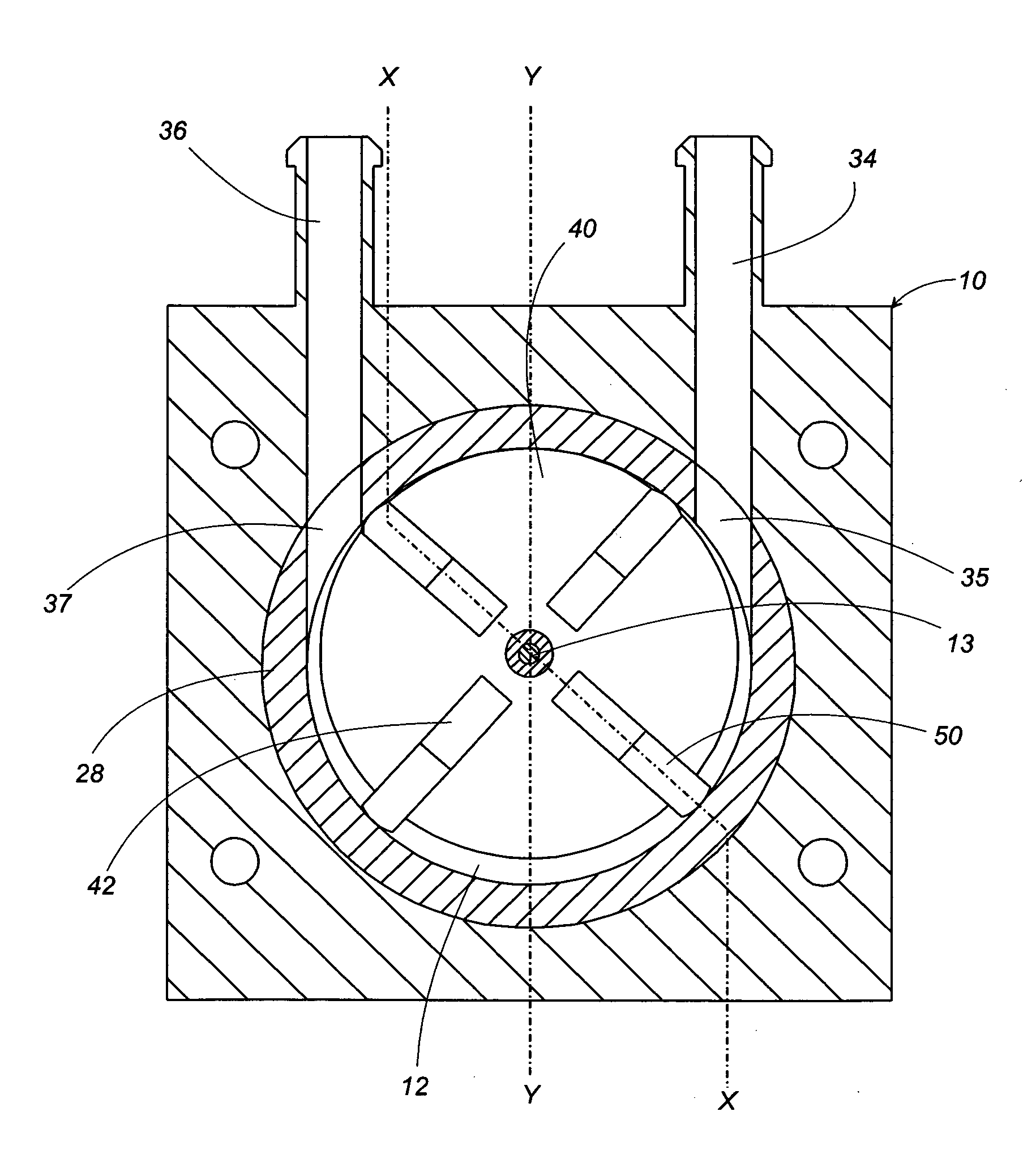
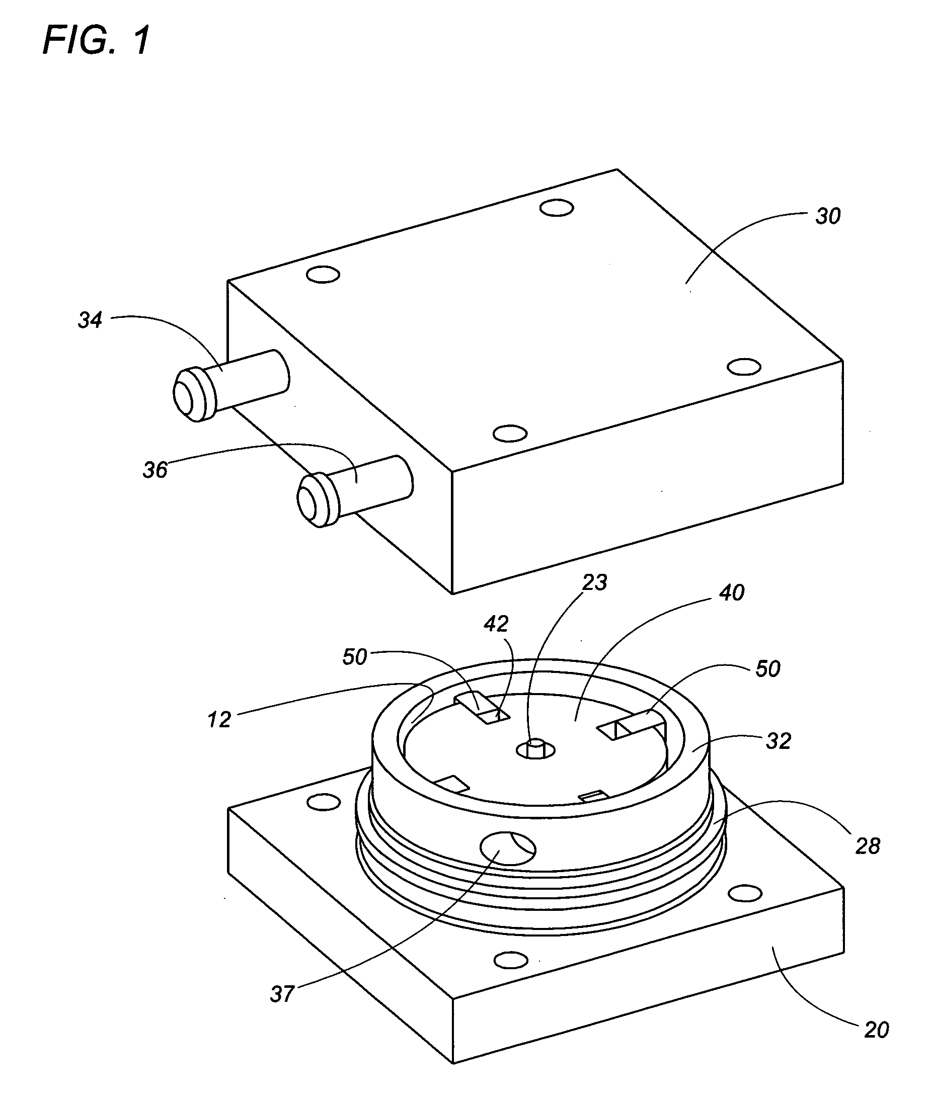
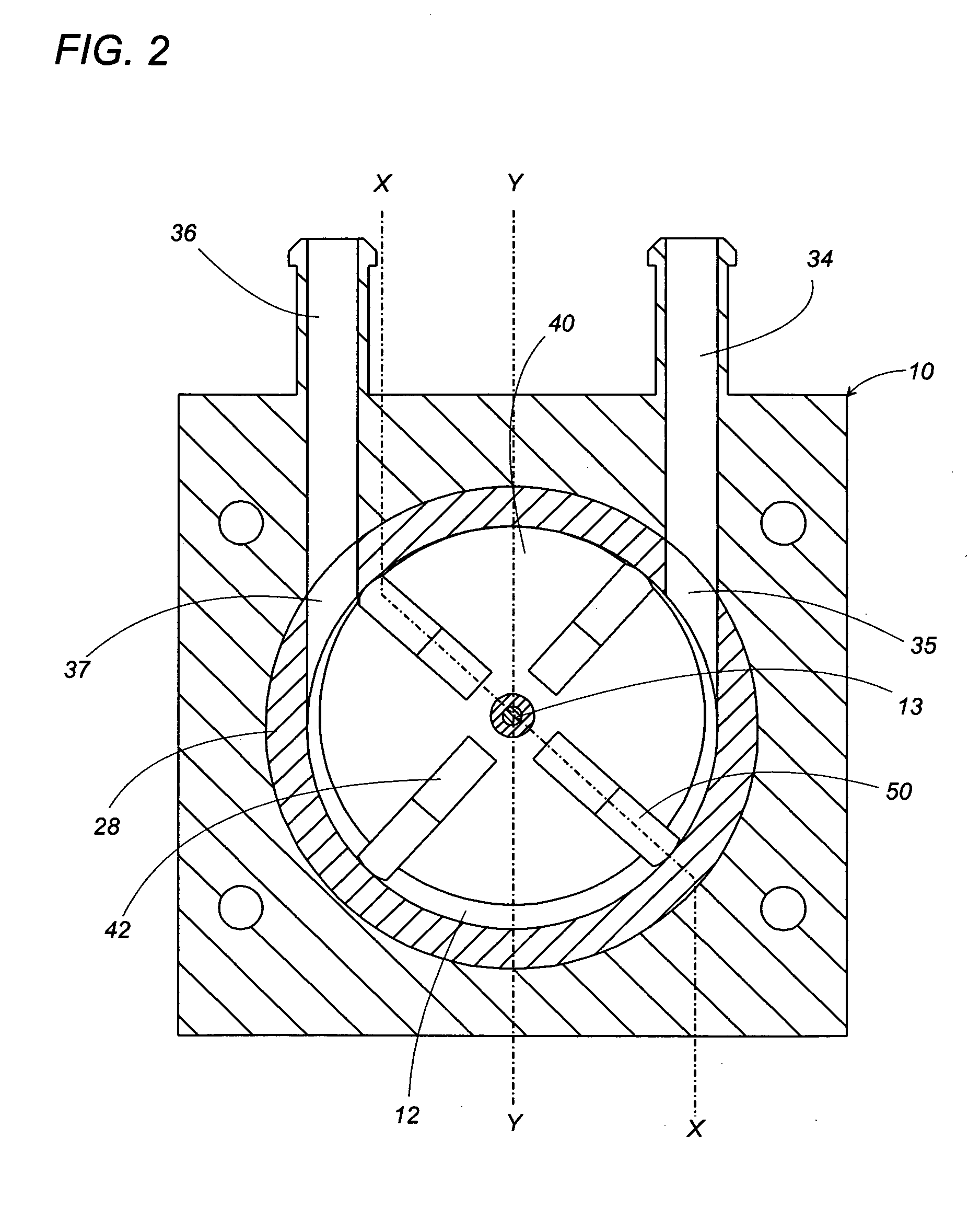
[0018]Referring now to FIGS. 1 to 4, there is shown a magnetic drive vane pump in accordance with a first embodiment of the present invention. The pump includes a casing 10 formed in its interior with a cylindrical pump cavity 12 which accommodates therein a rotor 40 having an eccentric axis offset from an axis of the pump cavity 12. The casing 10 is composed of a lower half 20 and an upper half 30 which are secured to each other with a sealing ring 14 held therebetween. The lower and upper halves 20 and 30 are respectively formed with a lower recess 21 and an upper recess 31 which are cooperative to define the pump cavity 12. As seen in FIGS. 3 and 4, the lower half 20 is formed to have a center stud 22 anchoring a shaft 23, and an annular projection 26 between the center stud 22 and a peripheral wall 28. The shaft 23 projects from the center stud 22 into a center concavity 29 of the lower half 20 to define the eccentric axis, and is surrounded by a bearing sleeve 24. A ring 32 is ...


PUM


Abstract

A magnet drive rotary vane pump has a casing with a pump cavity. A rotor carrying a plurality of vanes is disposed within the pump cavity to be rotatable about an eccentric axis with respect to the pump cavity for drawing the fluid into the pump cavity and expelling it out of the pump cavity. The rotor is configured to have a rotor magnet which is magnetically coupled to a stator magnet mounted on the casing outwardly of the pump cavity for driving the rotor. The rotor magnet is configured to have its major portion disposed in an overlapping relation with the stator magnet. Thus, the rotor magnet can be mechanically isolated from the stator magnet disposed outside of the casing to establish a sealless coupling therebetween for realizing leakage free pump.

Description

TECHNICAL FIELD[0001]The present invention is directed to a magnetic drive vane pump.BACKGROUND ART[0002]Vane pumps are widely known in the art, for example, as disclosed in Japanese patent publication No. 53-2704 A. Generally, the vane pump includes a casing with a pump cavity and a rotor rotatable about an eccentric axis within the pump cavity. The rotor carries a plurality of vanes which moves radially so as to have their outer ends kept in sealed contact with an interior wall of the pump cavity as the rotor rotates, thereby drawing a fluid into the pump cavity, compressing and expelling it out of the pump cavity. The rotor is coupled to an external motor to be driven thereby to rotate. For this purpose, the rotor is provided with a shaft which extends outwardly of the casing for coupling with the motor. Therefore, a sealing is between the shaft and the casing. However, as the shaft is a constantly moving part, there is always a problem that the sealing may become deteriorated du...

Claims


Application Information

Patent Timeline
Patent Type & Authority Applications(United States)
IPC IPC(8): F04C27/00F04B17/00F04C18/00F01C19/00
CPCF04C15/008F04C2/3442F04C18/344F04C18/50
Inventor NISHIKATA, MASAAKIKUSAKABE, TSUYOSHIHOJO, TSUKASAYAMAMOTO, KEN
Owner MATSUSHITA ELECTRIC WORKS LTD
Why Eureka
Try Eureka