Confectionery depositing apparatus and product and method of producing same

a depositing apparatus and confectionery technology, applied in the direction of sweetmeats, transportation and packaging, chewing gum, etc., can solve the problems of inability to meet the requirements of confectionery gravity feed, valve leakage and tailing, undesirable product rejection levels, etc., to eliminate dwell time, low accuracy of current systems, and high weight variance

Inactive Publication Date: 2008-09-11
WM WRIGLEY JR CO
View PDF27 Cites 4 Cited by
  • Summary
  • Abstract
  • Description
  • Claims
  • Application Information

AI Technical Summary

Benefits of technology

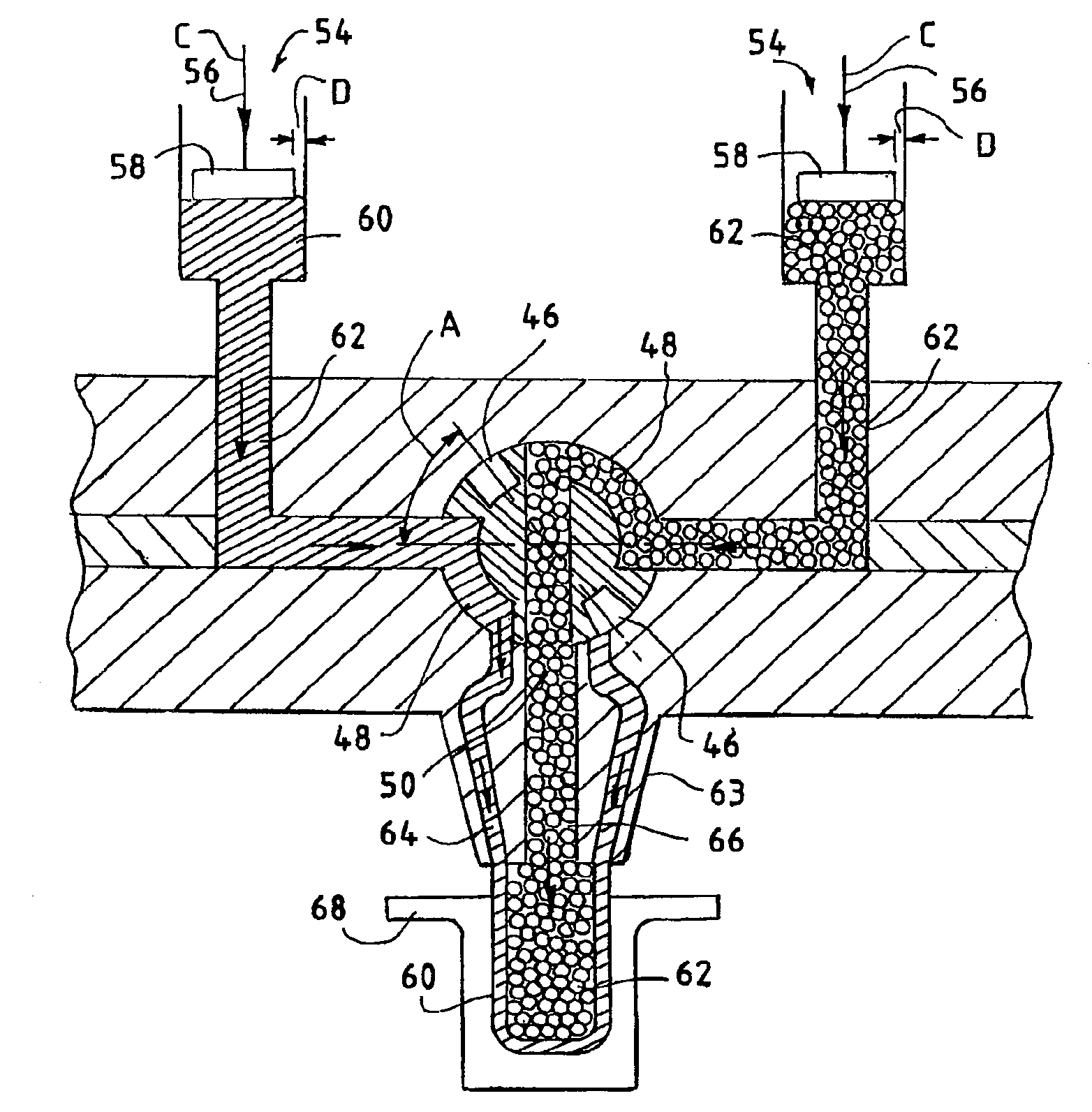
[0044]The small length of gap D or the absence of the gap altogether and the concomitant tight fit between piston head 58 and the inner surface of cylinder 28 enables apparatus 10 to deposit confectionery product with a high degree of accuracy. Piston head diameter (and cylinder diameter), stroke length, and confectionery density may be varied as desired to desposit confectionery product with a high degree of precision. An advantage of the present invention is that the only significant factor influencing variance between deposit runs or batches is stroke variance. Consequently, the present invention provides deposited confectionery product or articles having a weight variance between successive deposit amounts from about 0.01% to 1% with successive deposit amounts typically experiencing less than 0.6% weight variance. This is a substantial improvement over conventional confectionery depositing systems which typically experience weight variance from about 10% to about 20% or more.
[0045]Not wishing to be bound by any particular theory, the significant improvement in depositing precision provided by the present invention may be partially due to the avoidance of a gravity feed system by the present invention. Conventional gravity-fed confectionery depositors require a wide tolerance between the piston head and the inner cylinder surface in order to provide adequate space for confectionery to flow into the cylinder. Removal of the piston head from the cylinder chamber during conventional piston upstroke further contributes to high weight variance between successive deposit amounts. Moreover, the presence of openings in the cylinder walls for confectionery product inflow further contributes to the low accuracy of current systems. Conventional gravity-fed depositors also require dwell time to allow the flowable confectionery to enter the cylinder. The present invention eliminates dwell time as the closed pressure-feed system requires very little time to fill the cylinder with confectionery. The tight fit between the piston head and the inner cylinder surface, the closed pressure-fed confectionery delivery system, and the rotary valve each contribute to provide a confectionery depositing apparatus with exceptional accuracy.
[0046]Rotary valve 22 also contributes to the accuracy of the amount of confectionery deposited by apparatus 10. It is commonly known in the art that once the flowable confectionery is deposited from the nozzle, a small amount of confectionery product, known as a tail, may remain suspended from the nozzle outlet. This tail may eventually fall into the formed confectionery article. The tail may also remain on the nozzle to be deposited during the next deposit cycle. Either event may cause undesired disparity between the weight, size and appearance of the finished confectionery article. In addition, the tail may further deleteriously impact the surface texture of the finished article and any coating layer in particular.
[0047]In an embodiment of the present invention, the pistons may be moved in the first upward direction a short distance once the confectionery product is discharged from each cylinder. This is performed while the rotary valve is in the second or dispensing position. In this manner, the tail may be pulled into the transfer passage of the rotary valve thereby preventing the tail from adversely affecting the confectionery article formed.
[0048]Alternatively, the movement of the pistons in the downward direction may be synchronized with returning the rotary valve to the first position. Immediately upon completion of depositing the confectionery product from the cylinder, the rotary valve may be moved back to the first position to prevent formation of the tail altogether. In a further embodiment, movement of the rotary valve from the second or depositing position back to the first or transfer position may be coordinated with the small movement of the piston in the upward direction to ensure capture of the tail within the transfer passage.
[0049]In a further embodiment of the present invention, apparatus 10 may be configured to deposit more than one flowable confectionery product in order to produce a laminated confectionery article. Apparatus 10 may be adapted to dispense a plurality of flowable confectionery products. The number of cylinders, inlets, bores, ducts may be increased to provide an increased number of layers for the confectionery article as desired. In addition, rotary valve 22 may be adapted to include multiple transfer and dispensing passages to transfer and dispense multiple flowable confectionery products. For example, FIG. 7 shows rotary valve 22 having two transfer passages 46 and two dispensing passages 48.

Problems solved by technology

Customary gravity-feed arrangements for the fluid confectionery yield substantial inconsistency in the amount of confectionery drawn into the depositing apparatus.
In addition, spring loaded depositing valves used in current depositing apparatuses are prone to sealing problems resulting in valve leakage and tailing.
These and other shortcomings in the art lead to undesirable levels of product reject as uniformity in layer thickness cannot be controlled with a satisfactory degree of accuracy.

Method used


Image

  • Confectionery depositing apparatus and product and method of producing same
  • Confectionery depositing apparatus and product and method of producing same
  • Confectionery depositing apparatus and product and method of producing same

Examples


examples

[0063]

TABLE 1Deposit Amount Based on Piston Diameter and Stroke LengthConfectionery Density (hot mass) 1.27 gr / cm3STROKE (mm)SECTION (mm2)VOLUME (cm3)WEIGHT (g)Piston Diameter 6.00 mm.12.0028.2740.3390.43130.0028.2740.8481.077Piston Diameter 7.00 mm.12.0038.4850.4620.58730.0038.4851.1551.466Piston Diameter 8.00 mm.12.0028.2740.3390.43130.0050.2651.5081.915Piston Diameter 9.00 mm.12.0063.6170.7630.97030.0063.6171.9092.424Piston Diameter 10.00 mm.12.0078.5400.9421.19730.0078.5402.3562.992Piston Diameter 11.00 mm.12.0095.0331.1401.44830.0095.0332.8513.621Piston Diameter 12.00 mm.12.00113.0971.3571.72430.00113.0973.3934.309Piston Diameter 13.00 mm.12.00132.7321.5932.02330.00132.7323.9825.057Piston Diameter 14.00 mm.12.00153.9381.8472.34630.00153.9384.6185.865

TABLE 2Confectionary Article Example 1CONFECTIONERY ARTICLESAME PISTON STROKE, DIFFERENT PISTON DIAMETERSEXAMPLE 1(7 mm PISTON for 20% SHELL AND 14 mm PISTON for 80% CORE)Diameter of the piston A (shell)7mm.ToleranceFrom 7 − 0.005to...


PUM


Abstract

The present invention provides a confectionery depositing apparatus that deposits a layer or multiple layers of a flowable confectionery product with a high degree of accuracy. The apparatus includes a source of a flowable confectionery, a cylinder, and a rotary valve in fluid communication with the source of flowable confectionery, and the cylinder. Placement of the rotary valve in a first position permits the flowable confectionery into the cylinder and placement of the rotary valve in a second position permits dispensing of the flowable confectionery from the cylinder out of the apparatus. A piston in close operative engagement with the cylinder enables the apparatus to deposit precise amounts of confectionery product to produce thin uniform layers of confectionery product.

Description

BACKGROUND OF THE INVENTION[0001]Multiple layer confectioneries enjoy widespread appeal. Confectionery consumers are attracted to candies having multiple layers, flavors and colors arranged in various creative designs and shapes. Systems for producing such multiple component confectionery articles typically utilize a depositing apparatus that injection deposits two or more fluid confectionery streams into a mold to form the confectionery article. Formation of multiple layer candies requires an ability to control production parameters such as confectionery intake amount and confectionery injection rate, for example.[0002]Conventional depositing apparatuses used in the production of multiple layer candies, however, have several drawbacks. Customary gravity-feed arrangements for the fluid confectionery yield substantial inconsistency in the amount of confectionery drawn into the depositing apparatus. The confectionery deposit amount consequently varies significantly between deposit cyc...

Claims


Application Information

Patent Timeline
Patent Type & Authority Applications(United States)
IPC IPC(8): A23G4/18A23G3/54
CPCA23G1/202A23G1/206A23G3/0021A23G3/0027A23G3/54A23G3/0242A23G3/0257A23G3/2015A23G3/203A23G3/0068
Inventor FORNAGUERA, JOAN FABREYANG, MARGUERITE L.BENGOETXEA, MARIA JESUS
Owner WM WRIGLEY JR CO
Why Eureka
Try Eureka