
Downward angle settable hydraulic tensioner

a hydraulic tensioner and set-up technology, applied in the direction of belts/chains/gearrings, mechanical equipment, belts/chains/gearrings, etc., can solve the problems of inability to suppress the backlash of the timing chain c, accelerate oil leakage, and affect the operation of the tensioner, etc., to achieve optimal hydraulic balance and optimal hydraulic balance

Active Publication Date: 2008-09-11
TSUBAKIMOTO CHAIN CO
View PDF7 Cites 11 Cited by
  • Summary
  • Abstract
  • Description
  • Claims
  • Application Information

AI Technical Summary

Benefits of technology

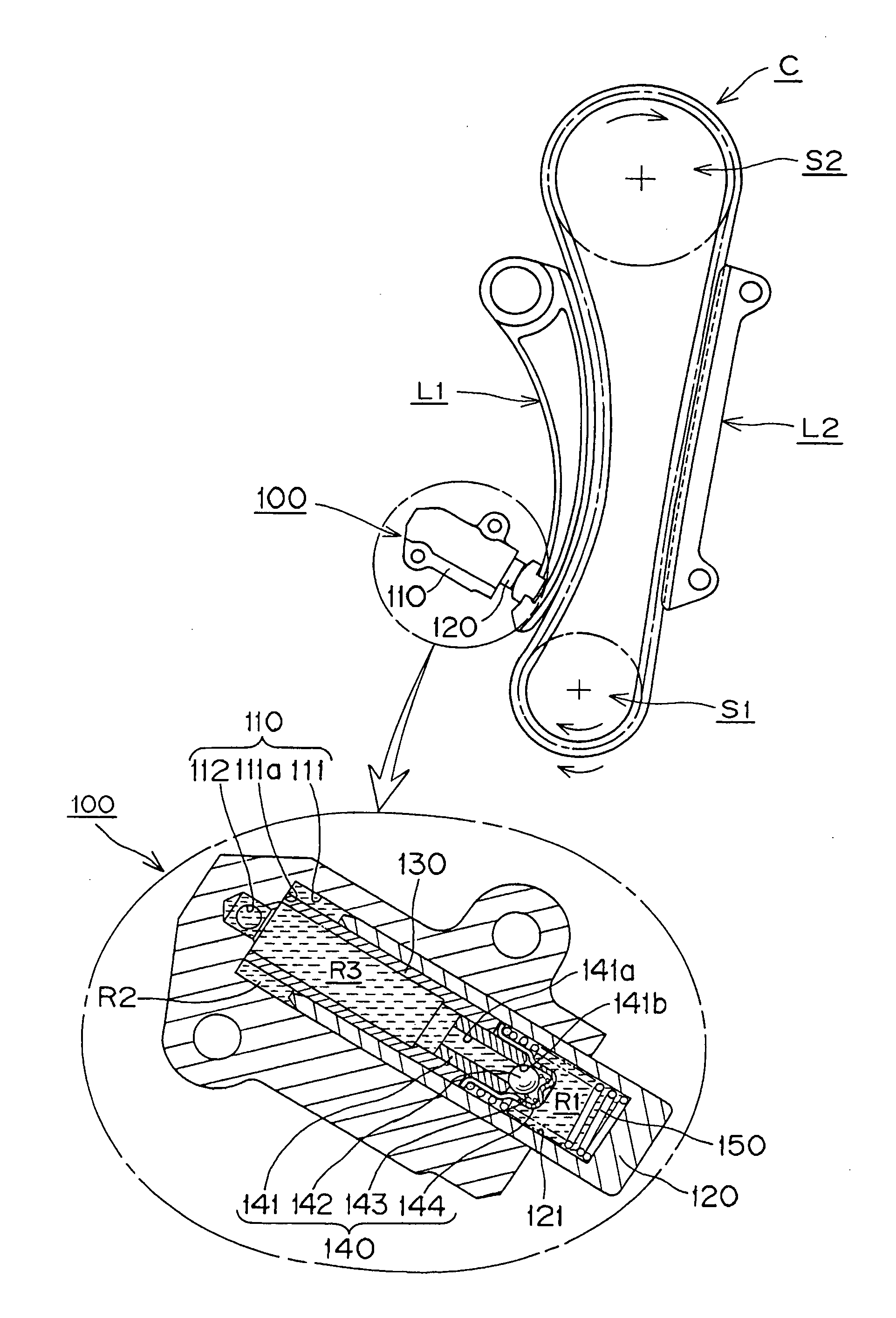
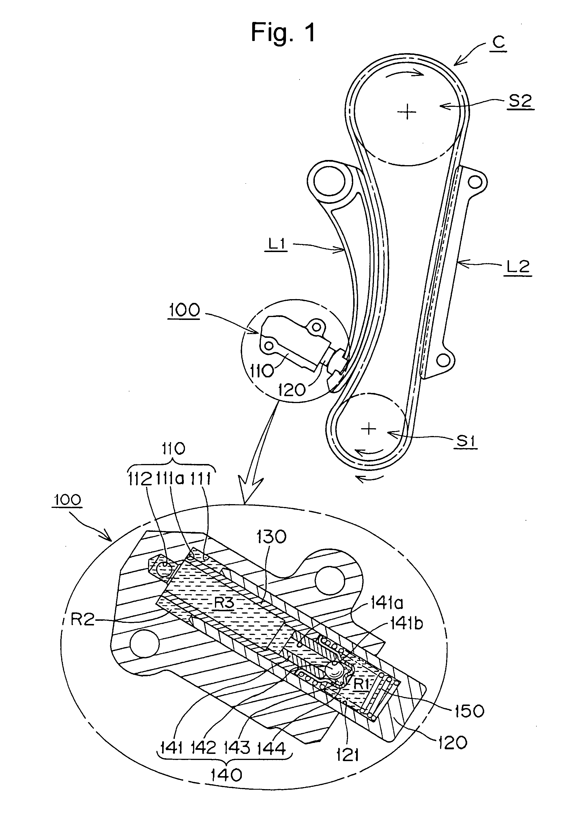
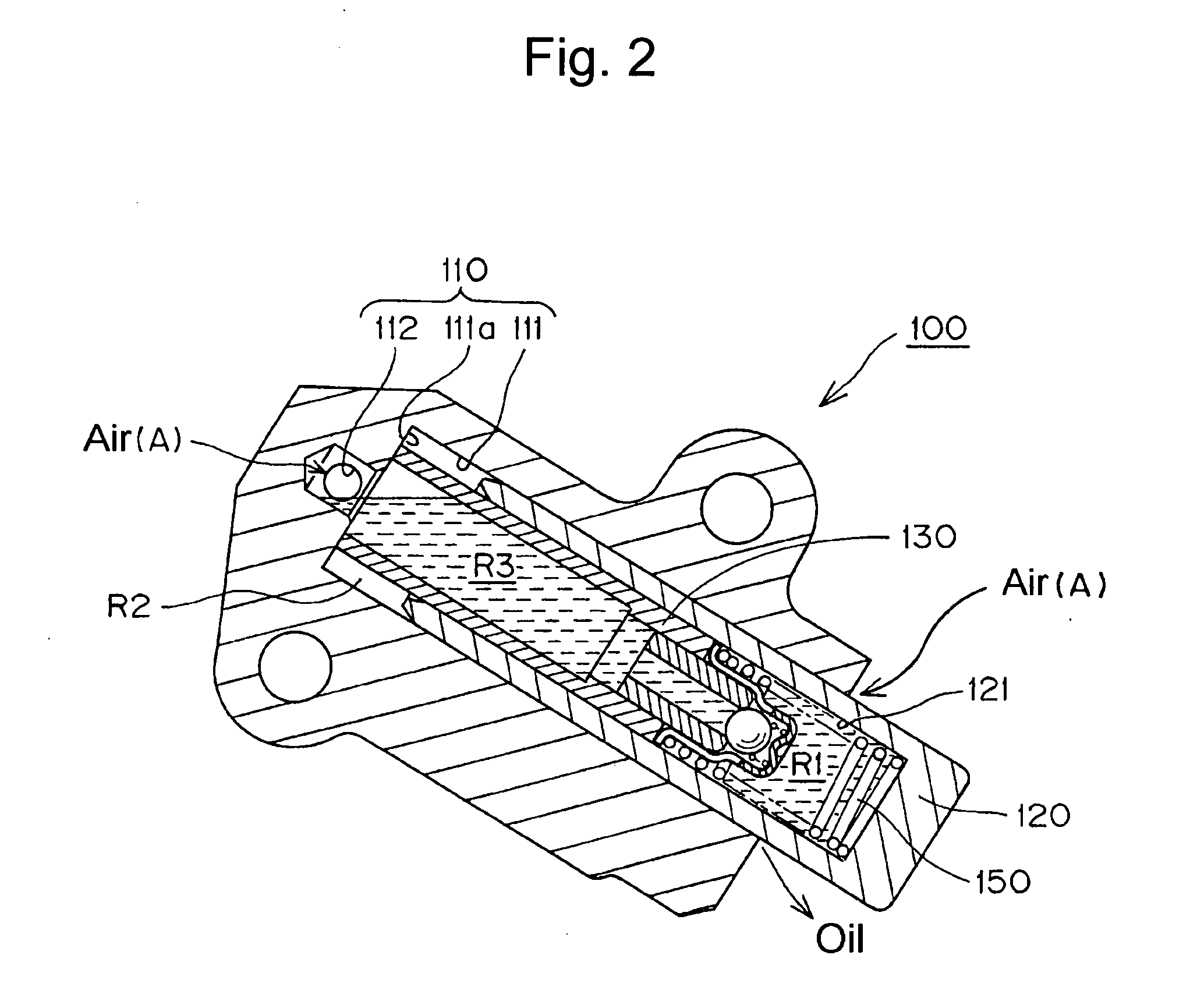
[0014]If the engine in which the tensioner is incorporated is left standing for a long period of time, oil leaks by gravity through a gap between a plunger-accommodating hole of the housing and the outer circumferential surface of the plunger. As a result of the leakage of oil, air is drawn from the outside into the region surrounding the upper end of the sleeve. However, the air does not enter the high pressure chamber, which is lower than the region surrounding the upper end of the sleeve. Thus, even upon starting of the engine after it has been standing in a stopped condition for a long time, the full damping force of the tensioner is exerted, and backlash of the timing chain and abnormal sounds can be prevented.
[0015]Furthermore, since the plunger slides between the inner circumferential wall of the plunger-accommodating hole and the outer circumferential surface of the sleeve, a labyrinth structure is formed, which suppresses excessive leakage of oil.
[0018]Additionally, since the bell-shaped retainer comprises a ball-surrounding portion, which supports the ball biasing spring and surrounds the check ball while allowing free movement of the check ball toward and away from the ball seat, and branched leg portions press-fit to the outer circumferential surface of the ball seat and providing oil introducing slots for replenishment and leakage of oil, when the plunger is pressed back into the plunger-accommodating hole, even though a plunger-biasing spring intervenes between the plunger and the bell-shaped retainer, the oil in the high pressure chamber can leak to the outside of the housing through the gap between the hollow portion of the plunger and the outer circumferential surface of the sleeve after flowing through the oil-introducing slots of the retainer. Thus, a sudden change in tension in the timing chain can be absorbed instantaneously, and an optimum hydraulic balance in the housing can be realized. Likewise, when excessive oil is supplied from an external oil source, it is supplied to the high pressure chamber through the oil-introducing slots. However, even through a plunger-biasing spring intervenes between the plunger and the bell-shaped retainer, a part of the excessive oil leaks outside the housing through a gap between the cylindrical hollow portion of the plunger and the outer circumferential surface of the sleeve after flowing through the oil introducing slots. Thus, excessive supply of oil to the high pressure chamber is suppressed and an optimum hydraulic balance in the housing can be further realized.

Problems solved by technology

A reduction in pressure within chamber R can result in an acceleration of oil leakage because, as the pressure decreases, more outside air is drawn into the chamber R, and, as a result, oil can flow out of the chamber by gravity at a faster rate.
The impairment of the operation of the tensioner due to accumulation of air in the high pressure chamber R is particularly significant upon engine start-up after the engine has been stopped and left standing for a long period of time.
When air accumulates in the high pressure oil chamber, backlash of the timing chain C cannot be suppressed and an abnormal sound is generated.
Additionally, the timing chain C can be unexpectedly damaged.
Another problem with the conventional hydraulic tensioner is that it consumes oil at a relatively high rate, and requires an oil pump having a high output.
Still another troublesome problem with the conventional hydraulic tensioner 500 was that, in manufacture, it was difficult to achieve a proper clearance between the cylindrical wall of the plunger-accommodating hole 511 and the outer circumferential surface of the plunger 520, as the clearance is affected by various factors including size and measurement errors, surface finishing, materials and the like.

Method used


Image

  • Downward angle settable hydraulic tensioner
  • Downward angle settable hydraulic tensioner
  • Downward angle settable hydraulic tensioner

Examples


Embodiment Construction

[0026]The tensioner according to the invention comprises a plunger, which protrudes slidably from a plunger-accommodating hole in a tensioner housing in a direction to apply tension to a traveling chain. The plunger has a cylindrical hollow portion which communicates with the plunger-accommodating hole of the housing. An inner sleeve fixed at the bottom end of the plunger-accommodating hole has an open end communicating with an oil supply passage in the housing, and extends slidably into the cylindrical hollow portion of the plunger. A check valve unit is fixed at the opposite end of the of the inner sleeve so that it protrudes into a high pressure chamber formed in the cylindrical hollow portion of the plunger. The check valve unit allows flow of oil into the high pressure chamber, but blocks reverse flow of oil from the chamber toward the oil supply passage. A plunger-biasing spring, which expands and contracts, is accommodated in the high pressure chamber. Even if the hydraulic t...


PUM


Abstract

The hollow plunger of a hydraulic tensioner for an engine timing chain protrudes from a tensioner housing in an oblique downward direction. An inner sleeve fixed to the housing slidably protrudes into the interior of the plunger, and has a ball check valve at its protruding end. Oil is supplied though the sleeve and the check valve to a high pressure oil chamber formed inside the plunger, and flows outward through a two-part leakage path formed by a gap between the sleeve and the interior of the plunger and a gap between the exterior of the plunger and an interior wall of a plunger-accommodating hole in the housing. Any air that enters the tensioner accumulates in a region surrounding the upper end of the sleeve, rather than in the high oil pressure chamber inside the plunger.

Description

CROSS-REFERENCE TO RELATED APPLICATION[0001]This application claims priority on the basis of Japanese application 2007-056236, filed Mar. 6, 2007. The disclosure of Japanese application 2007-056236 is hereby incorporated by reference.FIELD OF THE INVENTION[0002]This invention relates to a hydraulic tensioner of the kind used to apply proper tension to a timing belt, a timing chain, or the like, in a vehicle engine. More specifically, the invention relates to a downward angle settable hydraulic tensioner, i.e., a tensioner that can be mounted so that its plunger protrudes in an oblique downward direction.BACKGROUND OF THE INVENTION[0003]Hydraulic tensioners have been widely used to maintain proper tension, and suppress vibration, in engine timing chains, i.e., the endless chains used to transmit rotation from an engine crankshaft to one or more valve-operating camshafts.[0004]In a typical conventional hydraulic tensioner 500, as shown in FIGS. 6 and 7, a plunger 520 fits slidably in ...

Claims


Application Information

Patent Timeline
Patent Type & Authority Applications(United States)
IPC IPC(8): F16H7/22
CPCF16H7/0836F16H7/0848F16H2007/0859F16H2007/0812F16H2007/0806F16H7/08
Inventor NAMIE, TSUTOMUHASHIMOTO, HIROSHIMIYAKE, HIROYUKI
Owner TSUBAKIMOTO CHAIN CO
Learn More