Vehicle Control Apparatus and Vehicle Control Method

a technology of vehicle control and control apparatus, which is applied in the direction of vehicular safety arrangements, pedestrian/occupant safety arrangements, instruments, etc., can solve the problems of inability to accurately detect the position relationship between the host vehicle position and the starting and ending point of the connecting road, and inability to set the accurate control zon

Active Publication Date: 2008-09-11
TOYOTA JIDOSHA KK
View PDF10 Cites 42 Cited by
  • Summary
  • Abstract
  • Description
  • Claims
  • Application Information

AI Technical Summary

Benefits of technology

[0021]The invention makes it possible to set an appropriate control zone when performing vehicle assist control on an entrance ramp or an exit ramp connected to a main road having a different safe cruising speed limit than the entrance ramp or the exit ramp.

Problems solved by technology

As a result, depending on the accuracy of the road information and the detection accuracy of the host vehicle position, the positional relationship between the host vehicle position and the starting and ending points of the connecting road may not be able to be accurately detected.
As a result, an accurate control zone may not be able to be set.

Method used


Image

  • Vehicle Control Apparatus and Vehicle Control Method
  • Vehicle Control Apparatus and Vehicle Control Method
  • Vehicle Control Apparatus and Vehicle Control Method

Examples


first example embodiment

[0052]FIG. 4 is a plain view of a typical road shape of an exit ramp and an entrance ramp to / from a service area or parking area, in which the number of through lanes does not change before or after the exit point or merging point. The black circles in the drawing represent nodes relating to road information.

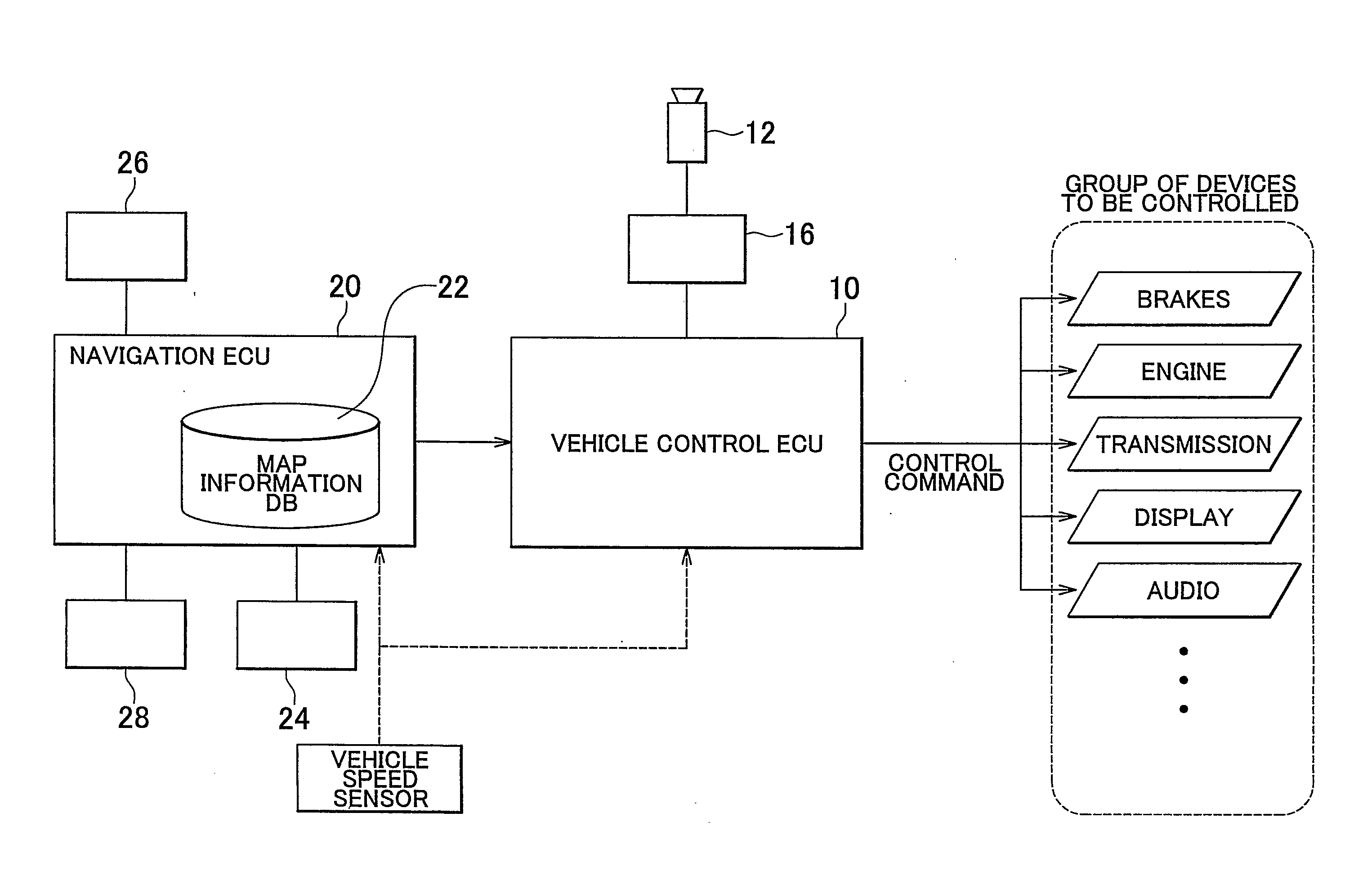
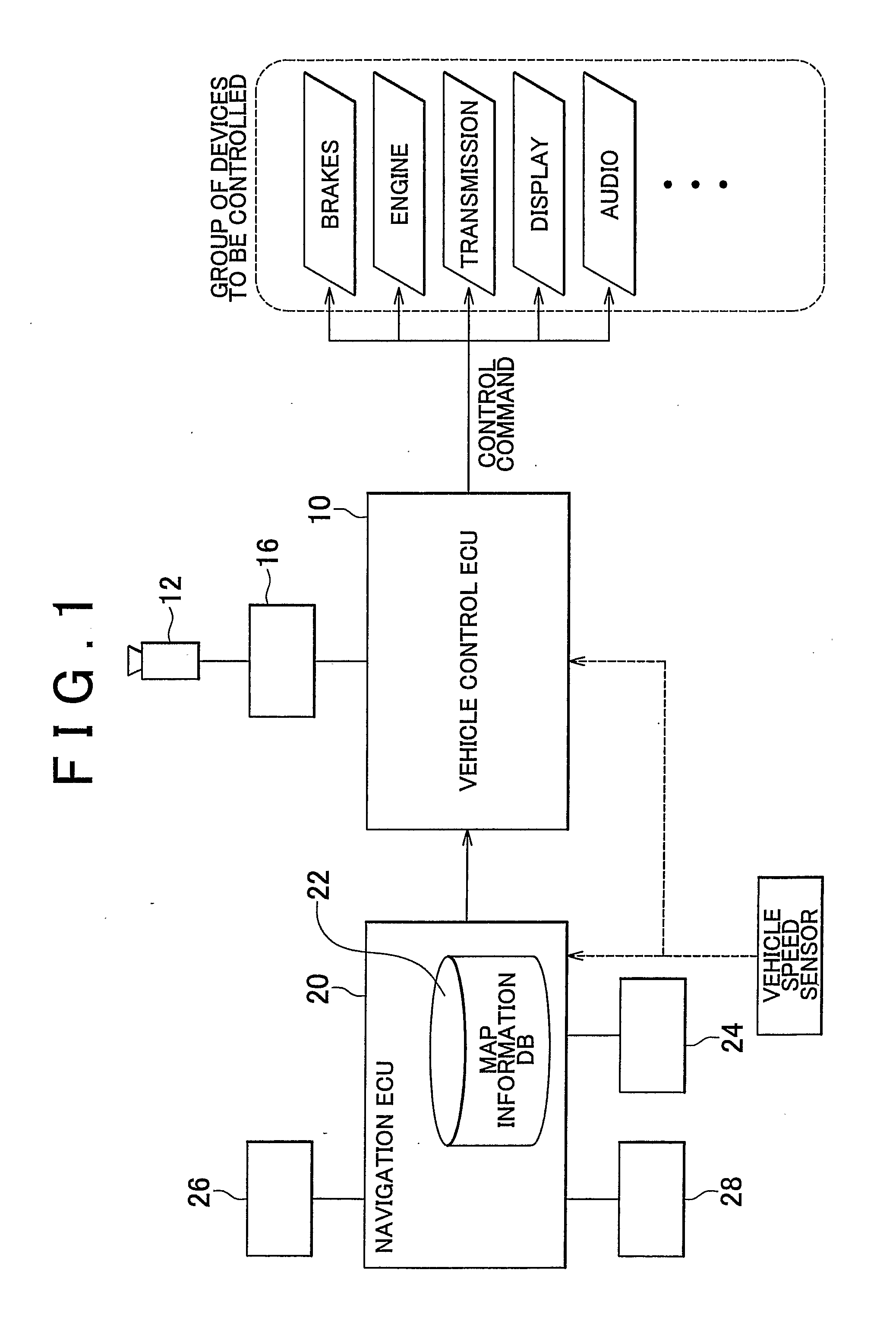
[0053]The exit ramp control start condition is satisfied when the back camera 12 captures an image of the broken line 70 when the host vehicle position is on a main road link related to a typical service area or parking area based on the map data, i.e., when the image processing device 16 recognizes a broken line in the image captured by the back camera 12 in a zone around a service area or parking area while the vehicle is traveling on a main road. This is because when the vehicle exits the main road to an exit ramp, the vehicle always crosses over the broken line 70 which is marked on the road at the exit ramp, as shown in FIG. 4, and divides the exit ramp from the main road.

[...

second example embodiment

[0064]FIG. 5 is a plain view of a typical road shape of an exit ramp and an entrance ramp to / from an interchange in which the number of through lanes does not change before or after the exit point or the merging point. The black circle in the drawing represents a node relating to road information.

[0065]The exit ramp control start condition is satisfied when the back camera 12 captures an image of the broken line 70 in a zone near an interchange when the vehicle is traveling in a through lane while the host vehicle position is on a through lane link related to a typical interchange based on the map data, i.e., when the image processing device 16 recognizes a broken line in the image captured by the back camera 12 while the vehicle is traveling in a through lane. This is because when the vehicle exits the through lane onto an exit ramp, the vehicle always crosses over the broken line 70 which divides the exit ramp from the main road at the entrance ramp, as shown in FIG. 5.

[0066]The e...

third example embodiment

[0076]FIG. 6 is a plain view of a service road for a parking area in a particular case in which there is only a service road and not a peripheral road of a parking area due to the fact that the parking area is extremely narrow. The black circles in the drawing represent nodes relating to road information.

[0077]The exit ramp control start condition is satisfied when the back camera 12 captures an image of the broken line 70 while the vehicle position is on a main road link relating to a small parking area based on the map data, i.e., when the image processing device 16 recognizes a broken line in the image captured by the back camera 12 while the vehicle is traveling on a main road in a zone near a small parking area. This is because when the vehicle exits a main road onto an exit ramp, the vehicle always crosses over the broken line 70 which divides the exit ramp from the main road even on a service road, as shown in FIG. 6.

[0078]The exit ramp control start condition may also includ...


PUM


Abstract

A vehicle control apparatus that performs driving assist control on an entrance ramp or an exit ramp connected to a main road having a different safe cruising speed limit than the entrance ramp or the exit ramp. The control apparatus includes a broken line detecting device that detects a broken line marked on the road and divides the main road and the entrance ramp or the exit ramp and a controller that determines a control zone of the driving assist control based on the broken line detection results from the broken line detecting device. For example, the vehicle control apparatus detects the broken line that divides a main road and an exit ramp using the broken line detecting device and starts driving assist control using the controller when it is detected that an accelerator pedal has been released.

Description

BACKGROUND OF THE INVENTION[0001]1. Field of the Invention[0002]The invention relates to a vehicle control apparatus and vehicle control method which performs driving assist control on an entrance ramp or exit ramp connected to a main road where the safe cruising speed limit is different than it is on the entrance ramp or the exit ramp.[0003]2. Description of the Related Art Japanese Patent Application Publication No. JP-A-10-141491, for example, includes road information storing means for storing road information, host vehicle position detecting means for detecting the position of the host vehicle on the road, vehicle speed detecting means for detecting the vehicle speed, connecting road detecting means for detecting a connecting road that connects with a road having different attributes from the stored road information, control zone setting means for setting a control zone based on the host vehicle position and the detected connecting road, automatic transmission for select gear r...

Claims


Application Information

Patent Timeline
Patent Type & Authority Applications(United States)
IPC IPC(8): G06F19/00B60R21/00B60W30/00B60W30/14G08G1/16
CPCB60W10/06B60W10/10B60W10/18B60W30/10G08G1/168B60W2550/141B60W2550/402G08G1/167B60W40/06B60W2552/05B60W2556/50
Inventor IKEDA, YUKIHIROHARA, KOUICHI
Owner TOYOTA JIDOSHA KK
Why Eureka
Try Eureka