Combustion pressure sensor

a technology of combustion pressure sensor and axial displacement, which is applied in the direction of instruments, lighting and heating apparatus, machines/engines, etc., can solve the problem that the deformation of the housing cannot be transferred to the axial displacement of the pressure transmitting member, and achieve the desired detection accuracy and seal the effect of reliable sealing

Inactive Publication Date: 2008-09-18
DENSO CORP
View PDF11 Cites 11 Cited by
  • Summary
  • Abstract
  • Description
  • Claims
  • Application Information

AI Technical Summary

Benefits of technology

[0021]Preferably, the seal member has a resilient portion urged into pressure contact with the pressure transmitting member. With the resilient portion thus provided, the seal member is able to reliably seal the clearance between the pressure transmitting member and the housing while keeping a properly adjusted contact pressure acting between the seal member and the pressure transmitting member. It is preferable that the resilient portion has a resiliency determined such that the contact pressure acting between the seal member and the pressure transmitting member provides a hermetic seal between the seal member and the pressure transmitting member while allowing smooth sliding movement of the pressure transmitting member relative to the housing.
[0022]Preferably, the seal member has a bellows-shaped portion at a part thereof. With this arrangement, since the bellows-shaped portion is able to take up or absorb a deformation of the housing even when the seal member is in contact with the pressure transmitting portion, a displacement of the pressure transmitting member resulting from the deformation of the housing does not take place. The desired detection accuracy can thus be maintained.

Problems solved by technology

More specifically, since the seal member is not fixed to the pressure transmitting member and since the pressure transmitting member is slidable relative to the housing, a deformation of the housing can never be transferred to an axial displacement of the pressure transmitting member.

Method used


Image

  • Combustion pressure sensor
  • Combustion pressure sensor
  • Combustion pressure sensor

Examples


first embodiment

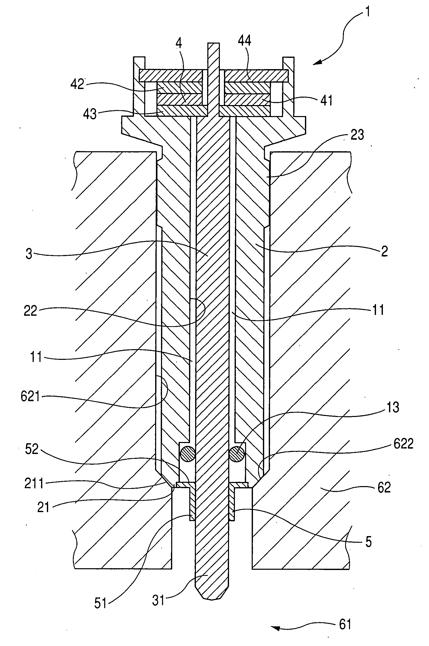
[0033]Referring now to the drawings and FIGS. 1 and 2 in particular, there is shown a combustion pressure sensor 1 according to the present invention. As shown in FIG. 1, the combustion pressure sensor 1 is used for the detection of the combustion pressure in a combustion chamber 61 of an internal combustion engine such as diesel engine. To this end, the combustion pressure sensor 1 generally comprises a housing 2, a pressure transmitting member 3, a load detecting section 4, and a seal member 5.

[0034]The housing 2 is a hollow cylindrical member adapted to be mounted to the internal combustion engine in such a manner that a front end portion 21 of the hollow cylindrical housing 2 is disposed in front of, or directed toward, the combustion chamber 61.

[0035]The pressure transmitting member 3 is an elongated rod-like member slidably inserted through an axial hole 22 of the hollow cylindrical housing 2 such that a pressure-receiving front end portion 31 of the rod-like pressure transmit...

second embodiment

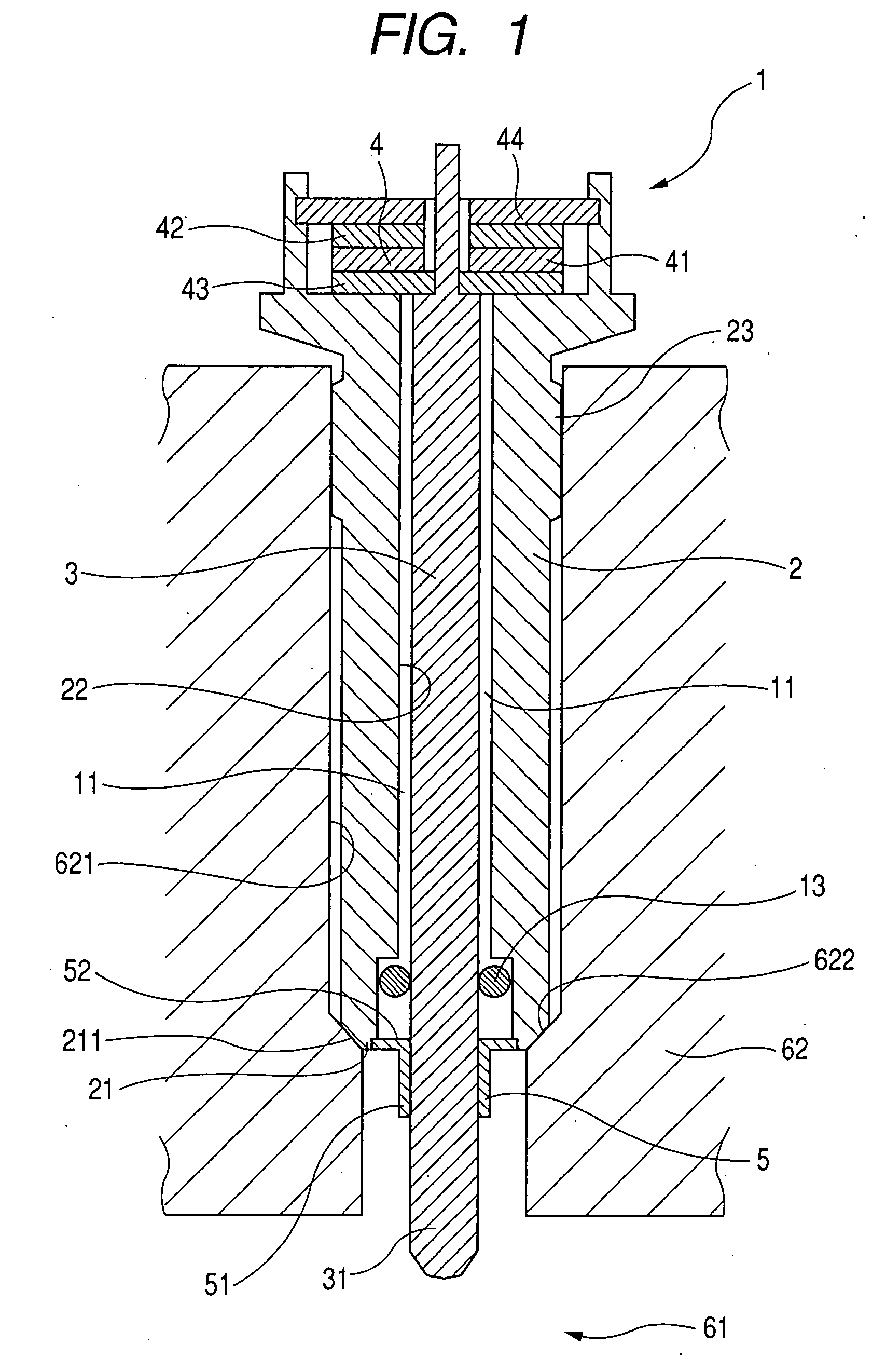
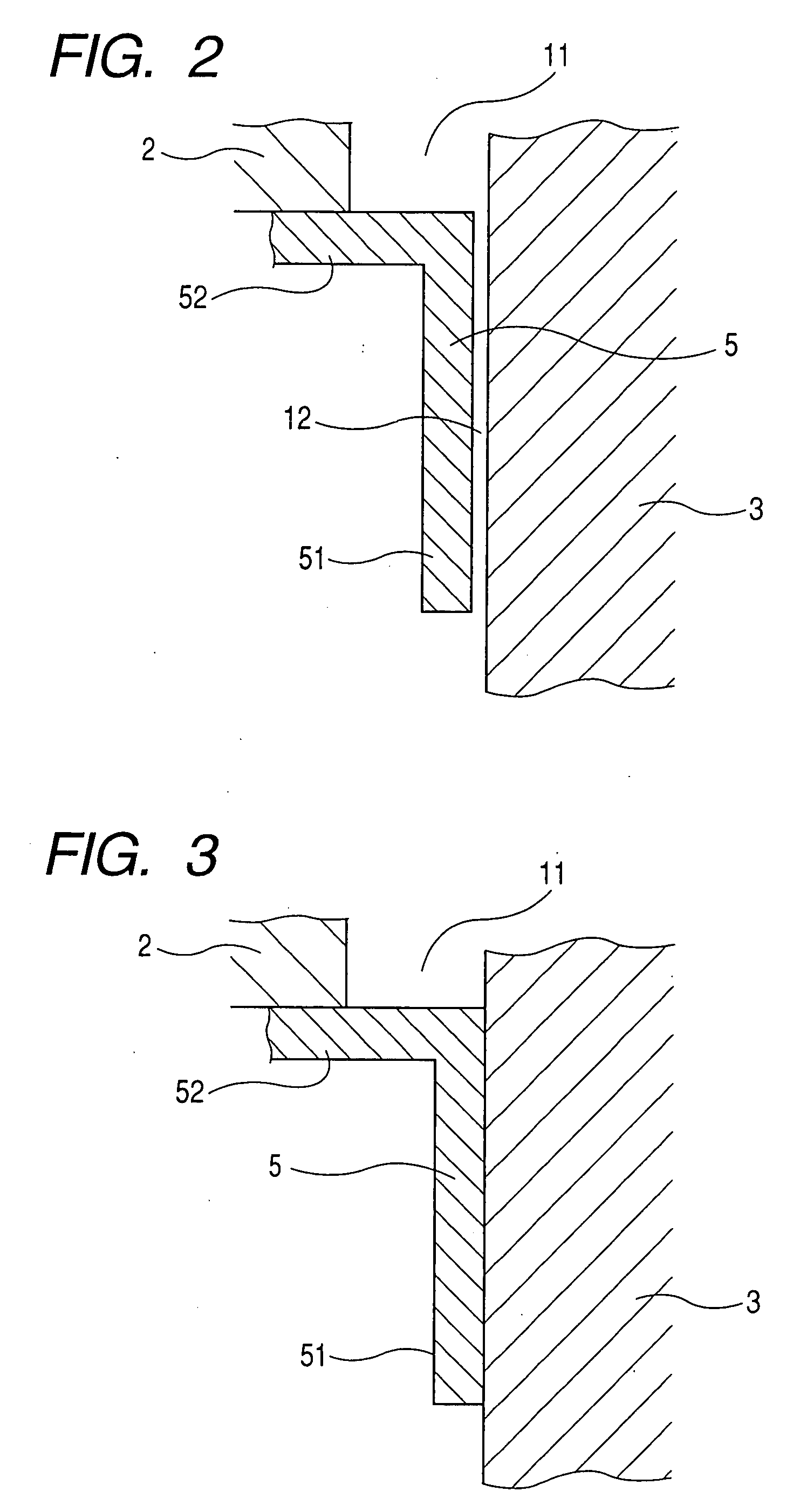
[0056]In the second embodiment shown in FIG. 4, by virtue of the bent portions 121 provided in the very small clearance 12, it is possible to effectively prevent combustion gas from flowing from the combustion chamber 61 into the axial hole 22 of the housing 2. Stated more specifically, due to a large pressure loss produced when the combustion gas passes through the very small clearance 12 including the bent portions 121, infiltration of the combustion gas from the combustion chamber 61 (see FIG. 1) into the housing 2 can be effectively prevented.

[0057]Furthermore, the bent portions 121 allow the clearance 12 to be larger in size than the straight bent-free clearance 12 of the first embodiment shown in FIG. 2. With this enlargement of the clearance 12, it is possible to sufficiently eliminate the risk of transmission of a deformation of the housing 2 to the load detecting section 4 via a displacement of the pressure transmitting member 3. This contributes to further improvement in t...

third embodiment

[0060]FIG. 6 shows in longitudinal cross section a portion of a combustion pressure sensor 1B according to the present invention. As shown in this figure, the combustion pressure sensor 1B includes a seal member 5 having a resilient portion 53 urged into pressure contact with an outer circumferential surface of the pressure transmitting member 3. The resilient portion 53 is formed at a lower end of the sealing portion 51, which is opposite to the annular attachment portion 52. The resiliency of the resilient portion 53 is determined such that a contact pressure acting between the seal member 5 and the pressure transmitting member 3 provides a hermetic seal between the seal member 5 and the pressure transmitting member 3 but does not hinder smooth sliding movement of the pressure transmitting member 3 relative to the housing 2.

[0061]Other structural parts of the combustion pressure sensor 1B of the third embodiment are the same as those of the combustion pressure sensor 1 of the firs...


PUM

PropertyMeasurementUnit
sizeaaaaaaaaaa
sizeaaaaaaaaaa
combustion pressureaaaaaaaaaa

Abstract

A combustion pressure sensor for detecting a pressure in the combustion chamber of an internal combustion engine includes a seal member sealing a clearance between a housing and a pressure transmitting member slidably inserted through an axial hole of the housing. The seal member is fixed to the housing at a position forward of a load detecting section disposed between the housing and the pressure transmitting member. The seal member is not fixed to the pressure transmitting member.

Description

CROSS REFERENCE TO RELATED APPLICATION[0001]The present application is based on and claims priority from Japanese Patent Application No. 2006-325608, filed Dec. 1, 2006, the content of which is incorporated herein by reference.BACKGROUND OF THE INVENTION[0002]1. Field of the Invention[0003]The present invention relates to a combustion pressure sensor for detecting the combustion pressure in a combustion chamber of an internal combustion engine such as diesel engine.[0004]2. Description of the Related Art[0005]Combustion pressure sensors mountable to an internal combustion engine such as diesel engine for detecting the combustion pressure in a combustion chamber of the internal combustion engine are known and used heretofore. One example of such known combustion pressure sensors is disclosed in Japanese Patent Application Publication JP 2005-090954 A (corresponding to US 2005 / 0061063 A1). As shown in FIG. 10 hereof, the disclosed combustion pressure sensor 9 includes a pressure trans...

Claims


Application Information

Patent Timeline
Patent Type & Authority Applications(United States)
IPC IPC(8): G01L7/08
CPCF02P19/028F23Q2007/002G01L23/10F23Q7/001
Inventor HIROSE, YOSHINOBUWATARAI, TAKEHIRO
Owner DENSO CORP
Why Eureka
Try Eureka