Liquid-jet device, image forming apparatus, and method for adjusting landing positions of liquid droplets

a liquid-jet device and image-forming technology, applied in the direction of printing mechanism, spacing mechanism, printing, etc., can solve the problems of difficult to obtain accurate color data of a test pattern, difficult to align lines printed by forward and backward scans, and worse problems

Inactive Publication Date: 2008-09-18
RICOH KK
View PDF14 Cites 53 Cited by
  • Summary
  • Abstract
  • Description
  • Claims
  • Application Information

AI Technical Summary

Benefits of technology

[0022]Embodiments of the present invention provide a liquid-jet device, an image forming apparatus, and a method for adjusting landing positions of liquid droplets (positions of jetted liquid droplets on a target surface) that solve or reduce one or more problems caused by the limitations and disadvantages of the related art.

Problems solved by technology

When printing lines with such a liquid-jet device or an image forming apparatus, misalignment tends to occur between lines printed by the forward and backward scans.
If an incorrect adjustment value is entered, it may worsen the problem.
One problem with the disclosed technology is that if the color of an ink is similar to that of the conveyor belt, it becomes difficult to obtain accurate color data of a test pattern.
However, this method increases the cost of a detecting unit or an imaging unit for obtaining color data of a test pattern.
Since such a conveyor belt has a black color similar to that of a black ink, it is difficult to correctly detect a black part of a test pattern based solely on reflected light from the test pattern or by scanning the test pattern with an imaging unit.
More specifically, with the image forming apparatus disclosed in patent document 1, since a test pattern formed on a recording medium conveying part is scanned by a sensor, it is difficult to obtain accurate color data of the test pattern if the color of an ink used to form the test pattern is similar to that of the conveying part.
Thus, the disclosed configuration makes it necessary to provide a filter for each color and therefore increases the production cost.
Also with this configuration, it is difficult to obtain accurate color data of the test pattern if the color of an ink used to form the test pattern is similar to that of the conveying part.
Also, since a laser beam used by the RGB sensor scans extremely small spots one by one, the result of scanning tends to be affected by a tiny foreign object or a flaw on the conveying part.
Further, an RGB sensor requires a light-receiving element for each color and is therefore expensive.
With this configuration, it is difficult to obtain accurate color data of the test pattern if the color of an ink used to form the test pattern is similar to that of the conveying part.
This in turn increases the cost of the inkjet recording apparatus.
However, if this method is applied to a liquid-jet image forming apparatus without change, it is not possible to accurately scan a test pattern since liquid droplets clump together.
Meanwhile, a method where a test pattern is formed by jetting ink droplets onto plain paper and is scanned by an optical sensor also has a problem.
With this method, bleeding caused by penetration of ink into the plain paper results in a blurred test pattern and makes it difficult to accurately detect the landing positions of ink droplets (positions of jetted ink droplets on a target surface).

Method used


Image

  • Liquid-jet device, image forming apparatus, and method for adjusting landing positions of liquid droplets
  • Liquid-jet device, image forming apparatus, and method for adjusting landing positions of liquid droplets
  • Liquid-jet device, image forming apparatus, and method for adjusting landing positions of liquid droplets

Examples


first embodiment

[0102]the present invention is described below. First, a mechanism for detecting and adjusting landing positions of liquid droplets in the image forming apparatus 200 is described with reference to FIGS. 6 and 7. FIG. 6 is a block diagram illustrating an exemplary mechanism for detecting and adjusting landing positions of liquid droplets. FIG. 7 is a drawing illustrating the exemplary mechanism for detecting and adjusting landing positions of liquid droplets in more detail.

[0103]As shown in FIG. 7 (see FIG. 9 also), the carriage 23 is equipped with the image sensor 401 (detecting unit) that detects a test pattern 400 (may also be called an adjustment pattern or a detection pattern) formed on the conveyor belt 31 made of a water-repellent material. The image sensor 401 includes a light-emitting element 402 for illuminating the test pattern 400 on the conveyor belt 31 and a light-receiving element 403 for receiving specularly reflected light from the test pattern 400. Actually, the li...

second embodiment

[0213]the present invention is described below with reference to FIG. 32.

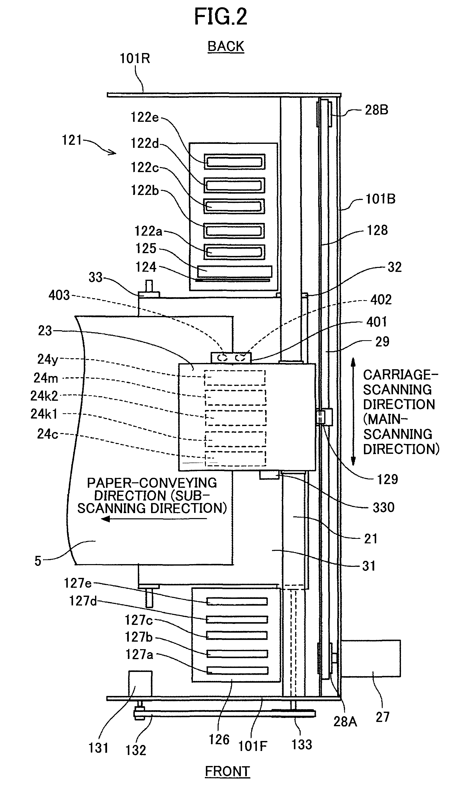
[0214]According to the second embodiment, the image forming unit 2 of the image forming apparatus 200 includes two image sensors 401 attached to a sensor support 800 disposed between the front board 101F and the rear board 101R. This configuration makes it possible to scan the test pattern 400 without being affected by the vibration of the carriage 23. This configuration can also be applied to a line-type image forming apparatus including a line-type recording head.

third embodiment

[0215]the present invention is described below with reference to FIG. 33.

[0216]An image forming apparatus of the third embodiment includes, instead of a conveyor belt, a conveyor roller 801 that conveys a recording medium (or a paper sheet) placed on or wound around it. In the image forming apparatus of the third embodiment, liquid droplets 500 are jetted onto the upper edge of the conveyor roller 801 such that the liquid droplets 500 are positioned at equal distances from the recording heads 24 (to be precise, from the image sensor 401). With this configuration, the proportion of specularly reflected light from areas where the liquid droplets 500 are not present is large, and the proportion of specularly reflected light from areas where the liquid droplets are present is small. Therefore, this configuration also makes it possible to accurately detect landing positions of liquid droplets.

[0217]A fourth embodiment of the present invention is described below with reference to FIGS. 34...


PUM


Abstract

A disclosed liquid-jet device includes a liquid-jet head configured to jet liquid droplets; a pattern formation control unit configured to control the liquid-jet head and thereby to form a test pattern composed of separate liquid droplets on a water-repellent part; a detecting unit including a light-emitting element configured to illuminate the test pattern on the water-repellent part and a light-receiving element configured to receive specularly reflected light from the illuminated test pattern and to output a detection signal proportional to the received specularly reflected light; and a landing position adjusting unit configured to adjust landing positions of the liquid droplets based on the detection signal from the light-receiving element.

Description

BACKGROUND OF THE INVENTION[0001]1. Field of the Invention[0002]The present invention generally relates to a liquid-jet device, an image forming apparatus, and a method for adjusting landing positions of liquid droplets.[0003]2. Description of the Related Art[0004]There are image forming apparatuses (e.g., a printer, a fax machine, a copier, and a multifunction copier having functions of a printer, a fax machine, and a copier) that use a liquid-jet device including a recording head implemented by a liquid-jet head to form (record or print) an image on paper (not limited to a sheet of paper but also refers to any medium on which an image can be formed, and may also be called a recording medium, recording paper, recording sheet, recording material, etc.). A liquid-jet device jets droplets of a recording liquid (or ink) from a liquid-jet head onto paper being carried in an image forming apparatus and thereby forms an image on the paper.[0005]In the present application, an image forming...

Claims


Application Information

Patent Timeline
Patent Type & Authority Applications(United States)
IPC IPC(8): B41J29/38B41J29/393
CPCB41J2/2135B41J19/207
Inventor MORINO, TETSUSAWAYAMA, NOBORUKAWABATA, KENICHIYORIMOTO, MAMORUHIROTA, TETSUROHAGIWARA, TAKUMISAKAKITANI, MASATOSHI
Owner RICOH KK
Why Eureka
Try Eureka