

Image forming apparatus
a technology of forming apparatus and forming rod, which is applied in the direction of printing mechanism, spacing mechanism, printing, etc., can solve the problems of difficult to accurately detect the position of the carriage, difficult to grasp the position of the dirt, and inaccurate detection of the signal from the linear encoder (reading the signal from the linear scale)
- Summary
- Abstract
- Description
- Claims
- Application Information
AI Technical Summary
Benefits of technology
Problems solved by technology
Method used
Image

Examples
first embodiment
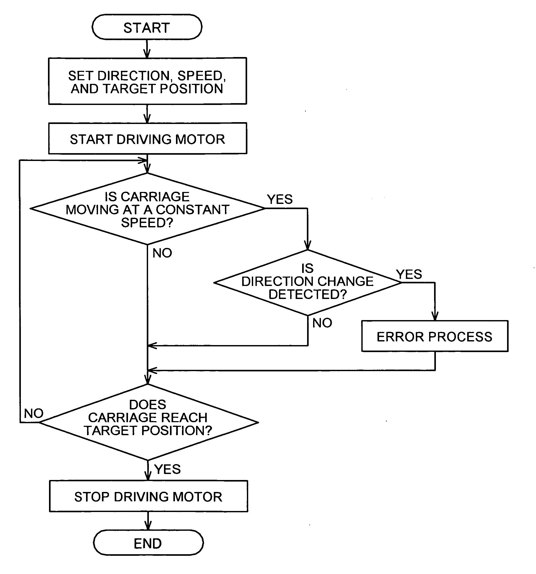
[0072]An operation of the first embodiment is explained with reference to a flowchart of FIG. 12, in which dirt on the encoder scale is detected by detecting a direction change during the movement of the carriage 3 at a constant speed.
[0073]The main scanning control unit 201 sets a moving direction, a speed, and a target position based on print data transmitted from the print data transmitting unit 202, and starts driving the main scanning motor 5. Then, the main scanning control unit 201 determines whether the main scanning motor 5 is operating for moving the carriage 3 at a constant speed. When the carriage 3 is moving at a constant speed, the main scanning control unit 201 determines whether the direction detecting unit 206 detects a change in the moving direction of the carriage 3. When the change in the moving direction is detected, that is, when the change in the moving direction of the carriage 3 is detected while the carriage 3 is moving at a constant speed, the main scannin...
second embodiment
[0079]An operation of the second embodiment is explained with reference to a flowchart of FIG. 13, in which dirt on the encoder scale 10 is detected by detecting a direction change before the carriage 3 reaches a preset moving direction change position.
[0080]The main scanning control unit 201 sets a moving direction, a speed, and a target position based on print data transmitted from the print data transmitting unit 202, and starts driving the main scanning motor 5. Then, the main scanning control unit 201 determines whether the position of the carriage 3 matches the preset moving direction change position. When the carriage 3 does not reach the moving direction change position yet, the main scanning control unit 201 determines whether the direction detecting unit 206 detects a change in the moving direction of the carriage 3. When the change in the moving direction is detected, that is, the change in the moving direction is detected before the carriage 3 reaches the preset moving d...
third embodiment
[0085]the present invention is explained with reference to FIGS. 14 to 26.
[0086]Determination of print timing and output of a drive waveform are explained with reference to FIG. 14. The print timing is determined using a rising edge of an encoder signal indicated by (a) in FIG. 14 (A phase or B phase of the encoder reading signal) as a reference. At the point that a given delay time Td has passed from the determined print timing as indicated by (b) in FIG. 14, a drive waveform output trigger is generated, which triggers output of a drive waveform that is a signal causing the recording head 4 to print. The drive waveform is thus output as indicated by (c) in FIG. 14. The delay time Td is set for ink-landing position adjustment in bidirectional printing.
[0087]When the carriage 3 is moving at a constant speed, an encoder signal rising edge arises at every constant edge interval time Te under an ideal condition.
[0088]However, when ink mist adheres to the encoder scale 10 as indicated by...
PUM
 Abstract
Description
Claims
Application Information