Surface light source device and LCD unit

a surface light source and light source technology, applied in the direction of lighting and heating apparatus, instruments, lenses, etc., can solve the problems of uneven decreased brightness/or thick thickness of the surface light source device, etc., to achieve uniform light emitted to the outside, improve usability of the plurality of line light sources, and high brightness

Inactive Publication Date: 2008-09-18
STANLEY ELECTRIC CO LTD
View PDF1 Cites 21 Cited by
  • Summary
  • Abstract
  • Description
  • Claims
  • Application Information

AI Technical Summary

Benefits of technology

[0041]According to the above-described exemplary surface light source device, the light emitted from each of the plurality of line light sources can enter into the light guide from the bottom surface of the light guide and the light can totally reflect on each inner surface of the plurality of two-dimensional curved surfaces of the light guide in side directions. The above-described light can be finally emitted upwards from the top surface of the light guide while repeating the total reflection time and time again in the light guide. Thus, a light-pass length from the light-emission of the light until the light-outgoing to the outside can become very long and the light can be enough mixed with respect to each other, the surface light source device of the disclosed subject matter can emit the light from the light guide with a uniform brightness.
[0044]According to the above-described exemplary surface light source device, a light emitted right above from each of the plurality of line light sources can diffuse / enter into the light guide from each of the plurality of two-dimensional concave channels of the bottom surface and can totally reflect on each of the plurality of two-dimensional curved surfaces without passing through the light guide. Thus, because the light emitted right above from each of the plurality of line light sources cannot directly pass through each base line of the top surface of the light guide, the surface light source device can prevent from occurring an irregular brightness. In this case, when each of the plurality of two-dimensional concave channels can be configured to form inverted v-shaped, the irregular brightness can be further prevented because of a decrease of the light passing right overhead and the like.
[0047]In the above-described exemplary surface light source device, when the surface light source device can further include at least one of light diffusing members and light condensing members on the light guide, the light emitted from the light guide to the outside can be controlled by the diffusing member and the light condensing member. In this case, because the diffusing member can further diffuse the light, the uniformity of the light emitted to the outside can improve and the directive characteristics of the light can be controlled by the light condensing member.
[0048]In addition, when the surface light source device further includes at least one reflecting member on the circuit board, a light passing through the bottom surface of the light guide can diffuse / reflect on at least the one reflecting member and can be entered into the light guide again. Thus, because the usability of the plurality of line light sources can be improved, the surface light source device of the disclosed subject matter can emit the light with more high brightness.
[0050]According to the above-described exemplary liquid crystal display unit, the above-described surface light source device can emit the light of the plurality of line light sources from the arbitrary large light guide with the high brightness and the uniform brightness. In addition, because the light guide can be formed the two-dimensional structure, various shapes of the light guide can be easily produced with low cost by the combination of only an extrusion molding and cutting process. Thus, the surface light source device can be employed as a light source for the back light unit for various LCD panels, and therefore the LCD unit can be used as a display unit for a television, computer monitor, display, etc.

Problems solved by technology

Consequently, because the number of light sources in an edge light type device is limited due to their location about a perimeter of the light guide, the surface light source device of the edge light type is sometimes not suitable for use as a back light unit when the device is of a large size and / or requires high brightness.
However, the direct light type surface light source device includes a problem in that a uniformity of the brightness thereof decreases when making a large size device and / or high brightness device.
On the other hand, when trying to make a surface light source device having uniform brightness, the brightness of the surface light source device decreases and / or a thickness thereof becomes thick.
Thus, because the above-described adjustment is tough work, the back light unit may result in increased cost for the product.
In addition, because the above described back light unit includes a process for manufacturing reflecting patterns, which is not required in a surface light source device of the conventional direct light type, and also includes a process for manufacturing the respective different reflecting patterns in each of the LED products, manufacturing costs for the back light unit may increase.
In addition, even when using the side-emission type LEDs, a part of the light emitted from each of the side-emission type LEDs that is not reflected on the top surface of the lens may leak out along a right overhead central axis near the top surface of the lens of the LED.
Thus, the back light unit may easily cause an irregular color, an irregular brightness, etc.
Moreover, because each of the side-emission type LEDs may require a complex structure and a complex lens shape, the cost of the back light unit that uses many side-emission type LEDs may increase along with many man-hours.
This is especially possible when high power LEDs are used for the plurality of LEDs in order to make the surface light source device 1 with a high brightness, and thus irregular brightness may be easily caused.
In addition, the surface light source device can become thin even when increasing the brightness thereof and when the emitting area thereof becomes large.

Method used


Image

  • Surface light source device and LCD unit
  • Surface light source device and LCD unit
  • Surface light source device and LCD unit

Examples


Embodiment Construction

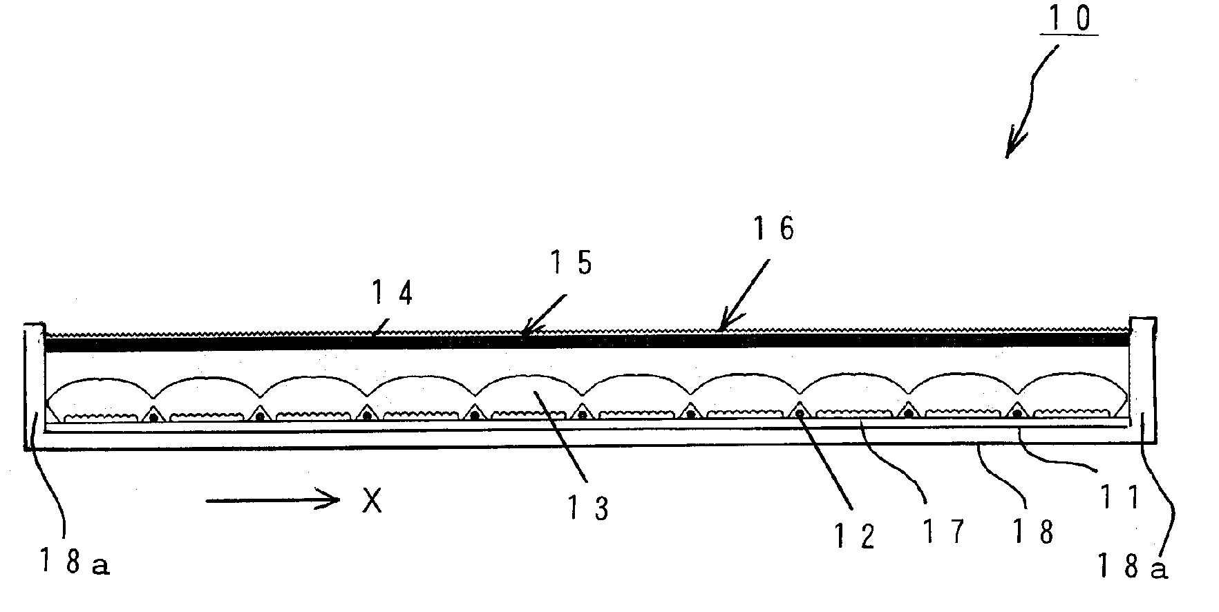
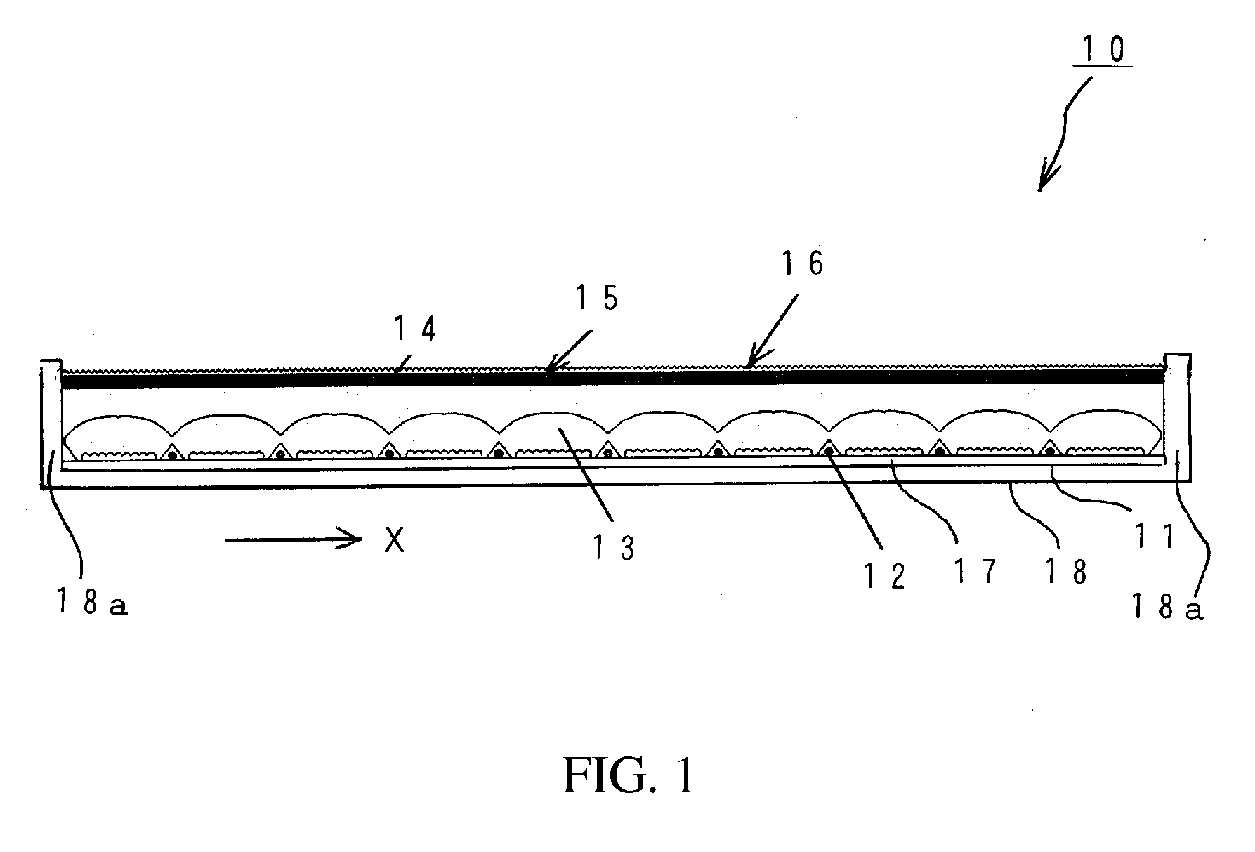
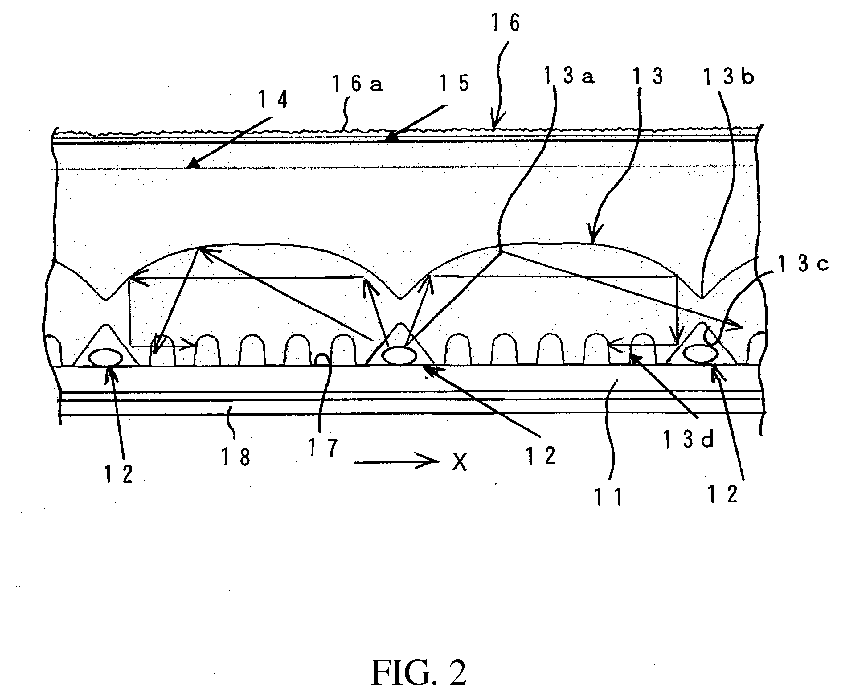
[0065]Exemplary embodiments of the disclosed subject matter will now be described in detail with reference to FIG. 1 to FIG. 9. FIG. 1 is a schematic cross-section view showing an exemplary embodiment of a structure for a surface light source device made in accordance with principles of the disclosed subject matter. The surface light source device 10 can be composed of a housing structure that can be configured to include or comprise a circuit board 11, a plurality of line light sources 12, a light guide 13, a diffusing plate 14, a diffusing sheet 15, a prismatic sheet 16, a reflecting member such as a diffusing reflection film 17, and a casing 18.

[0066]The circuit board 11 can be configured with a flat printed circuit board and can be configured to form conductive patterns for providing the plurality of line sources 12 with a power supply on a surface thereof. The circuit board 11 can also be covered with the diffusing reflection film 17 thereon. The plurality of line sources 12 ca...


PUM


Abstract

The disclosed subject matter includes providing a surface light source device with a high brightness and a uniform brightness and a LCD unit having the same qualities. The surface light device can include a plurality of line light sources mounted on a circuit board and a light guide located above the plurality of line light sources. The light guide can include a bottom surface for receiving light emitted from the plurality of line light sources and a top surface configured to reflect the light totally on an inner surface thereof. The light can be emitted upwards from the top surface after repeating many total reflections in the light guide. Therefore, the light that is emitted can have a uniform brightness. The surface light source device can define the brightness and the shape for the LCD unit according to variations of the plurality of line light sources and the light guide.

Description

[0001]This application claims the priority benefit under 35 U.S.C. §119 of Japanese Patent Application No. 2007-067585 filed on Mar. 15, 2007, which is hereby incorporated in its entirety by reference.BACKGROUND[0002]1. Field[0003]The presently disclosed subject matter relates to a surface light source device and a LCD unit including the same, and more particularly to a surface light source device which can be configured to exhibit high brightness and uniform brightness and can utilize a plurality of line light sources. Thus, the surface light source device can be employed as a light source for a back light unit located adjacent a liquid crystal display (LCD) of a television and the like. Therefore, a LCD unit including the same can exhibit high brightness and uniform brightness even on a large screen.[0004]2. Description of the Related Art[0005]Conventional optical transmission displays such as LCDs and the like are typically illuminated from a rear portion thereof by a surface lig...

Claims


Application Information

Patent Timeline
Patent Type & Authority Applications(United States)
IPC IPC(8): F21V8/00
CPCG02B3/005G02B6/0021G02B6/0038G02F1/133606G02B6/0071G02F1/133604G02B6/0068
Inventor ITO, TAKAHIRO
Owner STANLEY ELECTRIC CO LTD
Why Eureka
Try Eureka