Resource allocation control method and device in mobile radio communications system

Inactive Publication Date: 2008-09-18
NEC CORP
View PDF34 Cites 104 Cited by
  • Summary
  • Abstract
  • Description
  • Claims
  • Application Information

AI Technical Summary

Benefits of technology

[0016]An object of the present invention is to provide a resource allocation control method and device

Problems solved by technology

However, problems arise that required conditions are not satisfied and that the efficiency of resource usage declines, if resources are allocated in a fixed amount to a plurality of control signals which differ from each other in amount of information, transmission frequency, required condition of quality, and the like, such as the above-mentioned three types of control signals: ACK/NACK only, CQI only, and ACK/NACK and CQI (hereinafter, also referred to as “ACK/NACK & CQI” where appropriate).
As described above, if resources are allocated in a fix

Method used


Image

  • Resource allocation control method and device in mobile radio communications system
  • Resource allocation control method and device in mobile radio communications system
  • Resource allocation control method and device in mobile radio communications system

Examples


first exemplary embodiment

2. First Exemplary Embodiment

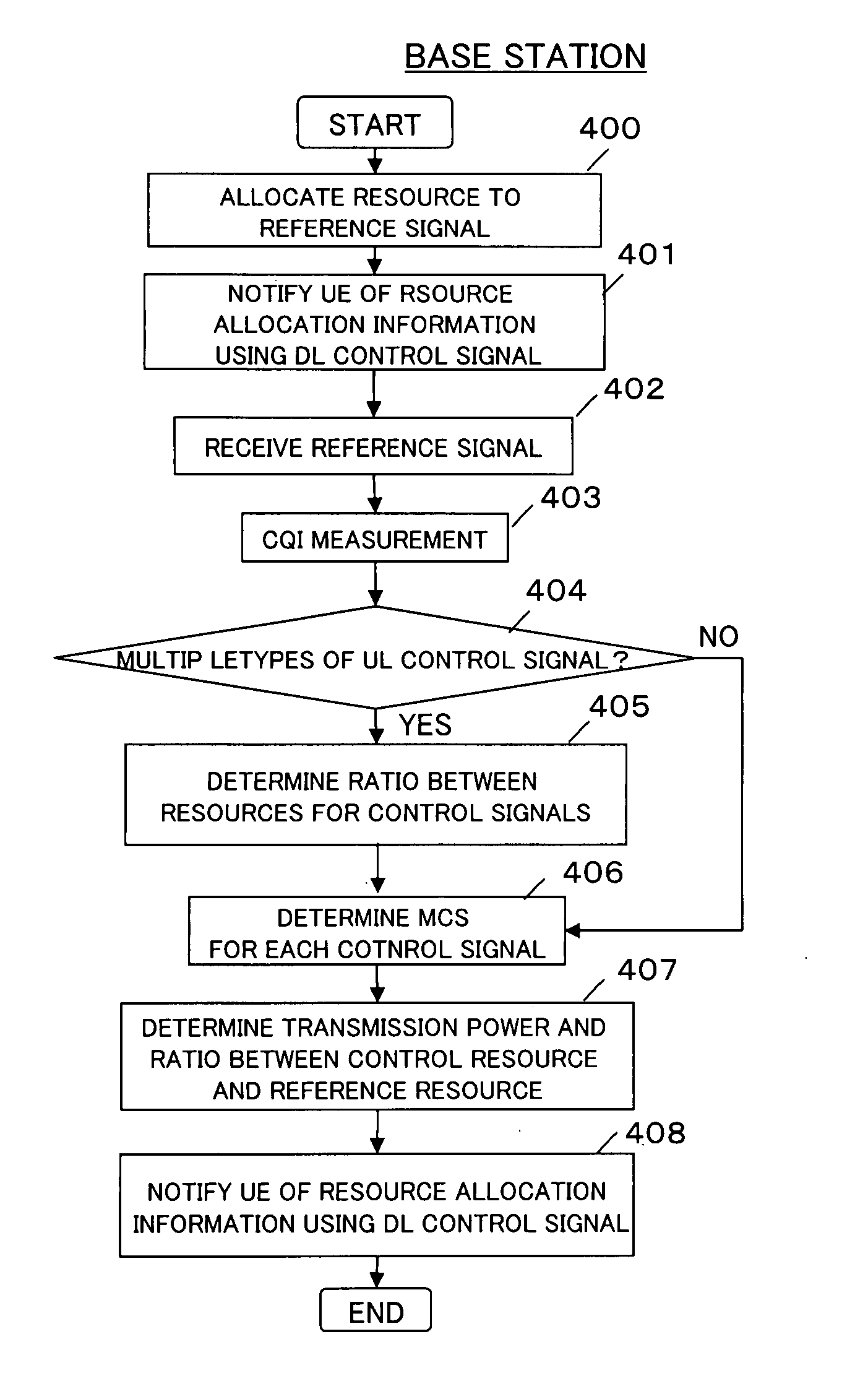
[0040]In a first exemplary embodiment of the present invention, a base station (also referred to as “NodeB”) takes initiative in controlling the ratio between control resources within a resource block, and in controlling the ratio between control and reference resources within a resource block.

2.1) Base Station

[0041]FIG. 3 is a block diagram showing a schematic configuration of a base station in a mobile radio system according to the first exemplary embodiment of the present invention. Here, it is assumed that the base station 100 accommodates N mobile stations (UEs) 1 to N.

[0042]At the base station 100, a radio communication section 101 demodulates an uplink control signal received from a mobile station, in accordance with a reference signal similarly received, and outputs the demodulated control signal and the reference signal to a control information extraction section 102 and a CQI measurement section 103 respectively. The control information extract...

second exemplary embodiment

3. Second Exemplary Embodiment

[0070]According to the above-described first exemplary embodiment, it is the base station that takes initiative in performing the control for apportioning the control and reference resources within a resource block. However, it is also possible that a mobile station takes initiative in performing similar control.

3.1) Base Station and Mobile Station

[0071]FIG. 9 is a block diagram showing a schematic configuration of a base station in a mobile radio system according to a second exemplary embodiment of the present invention. The base station in the second exemplary embodiment has a configuration similar to that of the base station in the first exemplary embodiment described with reference to FIG. 3, except that the base station in the second exemplary embodiment is not provided with the CQI measurement section 103. Therefore, in the second exemplary embodiment, those blocks having the same functions as in the first exemplary embodiment are denoted by the s...

third exemplary embodiment

4. Third Exemplary Embodiment

[0084]According to the above-described first and second exemplary embodiments, employed is a separate coding scheme by which, as shown in FIG. 4 or 10, the control signals CQI and ACK / NACK generated by the CQI generation section 205 and ACK / NACK generation section 206 respectively are encoded by the encoding sections 205a and 206a respectively (in which case a signal in each long block is multiplexed with others at LB level as shown in FIG. 7B or 12). However, the present invention is not limited to this scheme. It is also possible to employ Joint Coding by which multiple types of control signals are encoded by a single encoding section. According to this scheme, multiple types of control signals are multiplexed at bit level in each long block. Hereinafter, description will be given of the case where the joint coding scheme is employed in resource allocation control under the initiative of a base station as in the first exemplary embodiment. Note that th...


PUM


Abstract

For radio communications between a base station and a mobile station, resource allocation within a resource block including control resources used for control signals (CQI, ACK/NACK) and reference resources used for a reference signal is performed. The base station measures the quality of a channel between the mobile station and the base station itself. Based on the measured channel quality, the base station sets a ratio between resources for the control signals CQI and ACK/NACK in the control resources, and notifies the mobile station of the set resource ratio.

Description

BACKGROUND OF THE INVENTION[0001]1. Field of the Invention[0002]This application is based upon and claims the benefit of priority from Japanese Patent Application No. 2007-068879, filed on Mar. 16, 2007, the disclosure of which is incorporated herein in its entirety by reference.[0003]The present invention relates to a mobile radio communications system and, more particularly, to a control method and device of resource allocation among control signals and reference signals (pilot signals).[0004]2. Description of the Related Art[0005]In Long Term Evolution (LTE), which is currently being standardized by the 3rd Generation Partnership Project (3GPP), single-carrier transmission is employed as an uplink access scheme in broadband radio access. The single-carrier transmission is an access scheme excellent in power efficiency because the peak-to-average power ratio (PAPR) can be suppressed low in comparison with multi-carrier transmission such as orthogonal frequency division multiplexin...

Claims


Application Information

Patent Timeline
IPC IPC(8): H04Q7/00H04J11/00H04L27/01H04W16/02H04W28/06H04W72/04H04W72/12
CPCH04L1/0006H04L1/0026H04L1/0029H04L1/1671H04L1/1867H04L5/0007H04W92/20H04L5/006H04L5/0094H04L27/2613H04W24/10H04W72/042H04W72/085H04L5/0053H04W72/542H04W72/23H04L5/0035H04L1/0003H04W52/241H04L5/0048
Inventor INOUE, TAKAMICHIKAKURA, YOSHIKAZU
Owner NEC CORP
Why Eureka
Try Eureka