Object-Tracking Apparatus, Microscope System, and Object-Tracking Program

a technology of microscope system and object tracking, applied in the field of object tracking apparatus, microscope system, and object tracking program, can solve the problems of increasing the burden on the observer, difficulty in performing sufficient observation,

Inactive Publication Date: 2008-09-18
OLYMPUS CORP
View PDF3 Cites 41 Cited by
  • Summary
  • Abstract
  • Description
  • Claims
  • Application Information

AI Technical Summary

Benefits of technology

[0042]In the object-tracking apparatus, the microscope system, and the object-tracking program according to the present invention, an imaging target in each of images picked up at multiple time points can be tracked more precisely.

Problems solved by technology

However, the conventional visually-observing method has a difficulty in performing a sufficient observation due to a problem that an increase in the number of observing target, observation frequency, observation range, observation time and the like causes an increase in the burden on an observer.

Method used


Image

  • Object-Tracking Apparatus, Microscope System, and Object-Tracking Program
  • Object-Tracking Apparatus, Microscope System, and Object-Tracking Program
  • Object-Tracking Apparatus, Microscope System, and Object-Tracking Program

Examples


first embodiment

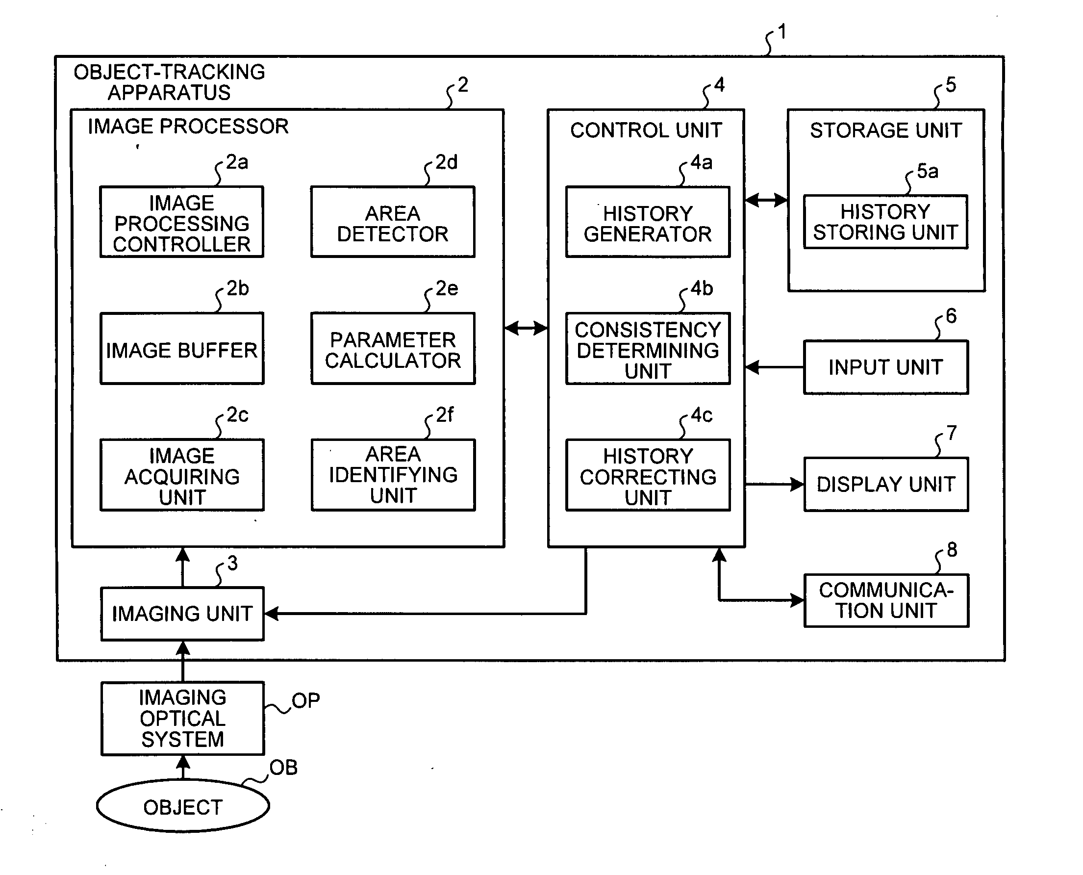
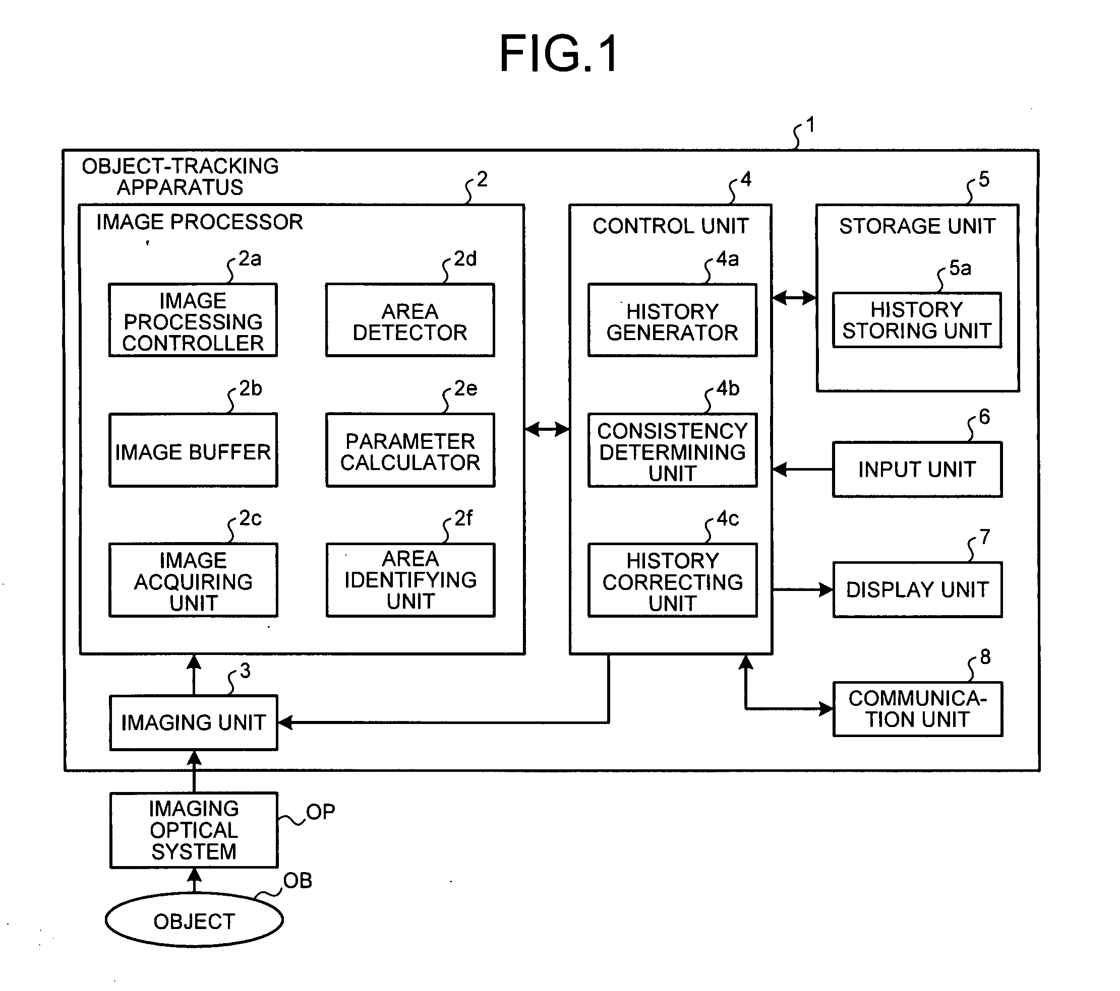
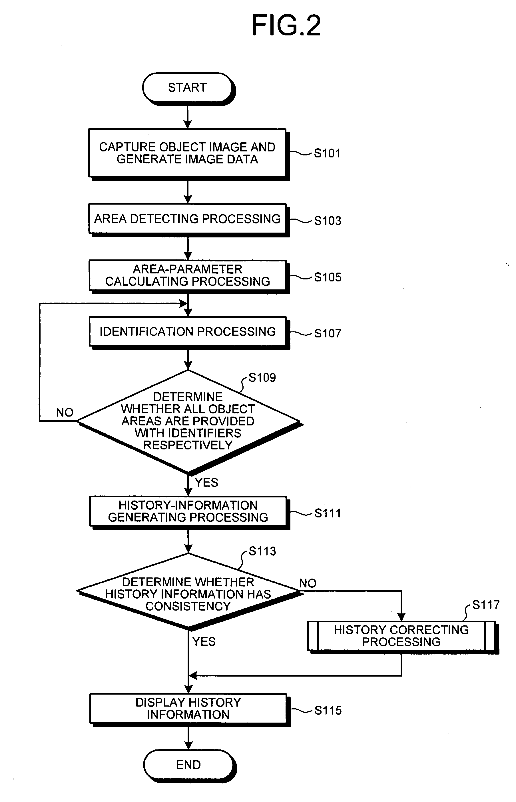
[0087]An object-tracking apparatus, a microscope system, and an object-tracking program according to a first embodiment of the present invention will be explained. FIG. 1 is a block diagram of a configuration of an object-tracking apparatus and a microscope system according to the first embodiment. As shown in FIG. 1, an object-tracking apparatus 1 according to the first embodiment includes an image processor 2 which analyzes and processes image data generated by an imaging unit 3; the imaging unit 3 which captures an image of an object OB to generate the image data; a control unit 4 which controls entire processing and operation of the object-tracking apparatus 1; a storage unit 5 which stores various types of information such as a tracking result; an input unit 6 which inputs various types of information; a display unit 7 which displays various types of information such as image information; and a communication unit 8 which performs communication of various types of information wi...

second embodiment

[0132]Next, a second embodiment will be explained. In the first embodiment described above, the history information is generated by making the property information of each time point of the object area associated with time series. Further, the second embodiment is configured to obtain information about a parent-child relationship which arises due to a cell division of at least one cell as a tracking target, and generate genealogy information corresponding to the history information.

[0133]FIG. 7 is a block diagram of a configuration of an object-tracking apparatus and a microscope system according to the second embodiment of the present invention. As shown in FIG. 7, an object-tracking apparatus 11 according to the second embodiment includes an image processor 12, a control unit 14, and a storage unit 15 in place of the image processor 2, the control unit 4, and the storage unit 5 respectively of the object-tracking apparatus 1. The image processor 12 includes a cell-division determi...


PUM


Abstract

An object-tracking apparatus (1; 11) includes, for observing an object area in an image and accurately track a tracking target, an image acquiring unit (2c) that acquires image data; an area detector (2d) that detects the object area from the image; a parameter calculator (2e) that calculates an area parameter which indicates a property of the object image; an area identifying unit (2f) that provides the object area at a processing target time point with an identifier which shows a correspondence between the object area at the processing target time point and the object area at an identification time point; a history generator (4a) that associates the identifier with the area parameter to generate property information, and associates the generated property information of respective time points with time series to generate history information; a consistency determining unit (4b) that determines a consistency in the history information from a determination time point to the processing target time point; and a history correcting unit (4c) that corrects the history information when the consistency determining unit (4b) determines no consistency.

Description

TECHNICAL FIELD[0001]The present invention relates to an object-tracking apparatus, a microscope system, and an object-tracking program, specifically to an object-tracking apparatus, a microscope system, and an object-tracking program which allow an observation of an image area corresponding to an imaging target in each of images picked up at multiple time points in time series and a tracking of the imaging target.BACKGROUND ART[0002]Conventionally, an observation of various living specimens has been performed by using a microscope and the like. In the observation of living specimens by using the microscope, a specimen whose observation target is stained in accordance with the intended purpose is normally disposed on a glass slide, and visually observed via a magnifying optical system. Such an observation using the microscope is often employed for the purpose of measuring a movement of a microbe, cell, and the like during incubation and a temporal change while a reagent is applied, ...

Claims


Application Information

Patent Timeline
Patent Type & Authority Applications(United States)
IPC IPC(8): G06K9/00
CPCG06T7/2033G06T2207/10016G06T2207/30241G06T2207/30024G06T2207/10056G06T7/246G06V20/69
Inventor OHNO, YOSHINORI
Owner OLYMPUS CORP
Why Eureka
Try Eureka