Micro power supply device

a power supply device and micro-chip technology, applied in the direction of high current circuit adaptation, fixed connection, coupling device connection, etc., can solve the problems of poor contact and the difficulty of reducing the volume of the whole device, and achieve the effect of simple and neat appearance of the power supply device and easy understanding for examiners

Inactive Publication Date: 2008-09-18
PORTWELL
View PDF5 Cites 1 Cited by
  • Summary
  • Abstract
  • Description
  • Claims
  • Application Information

AI Technical Summary

Benefits of technology

[0010]Another further objective of the present invention is to provide a micro power supply device, and the exterior of the power supply board is encapsulated with a plastic substance (such as silicone and plastic) and integrated with the electric connector to provide a simple and neat appearance of the power supply device.
[0011]To make it easier for the examiner to understand the object, shape, structure, device, characteristics and functions of this invention, the specification accompanied by the drawings is described as follows.

Problems solved by technology

Such arrangement not only causes a poor contact easily, but also results in a tremendous difficulty of reducing the volume of the whole device.

Method used


Image

  • Micro power supply device
  • Micro power supply device
  • Micro power supply device

Examples


Embodiment Construction

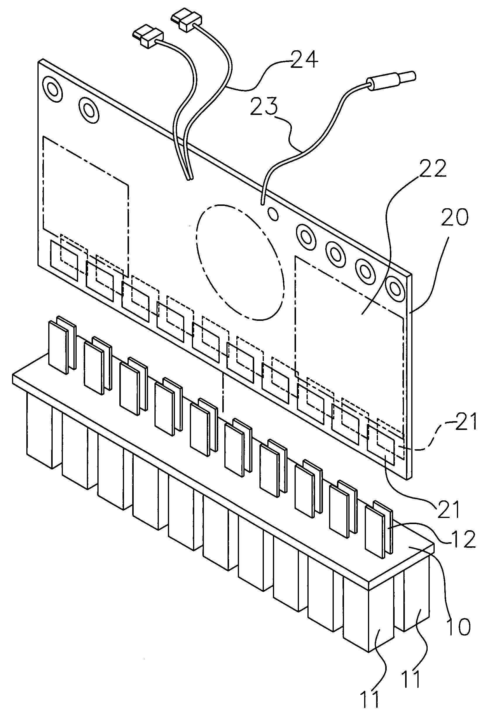
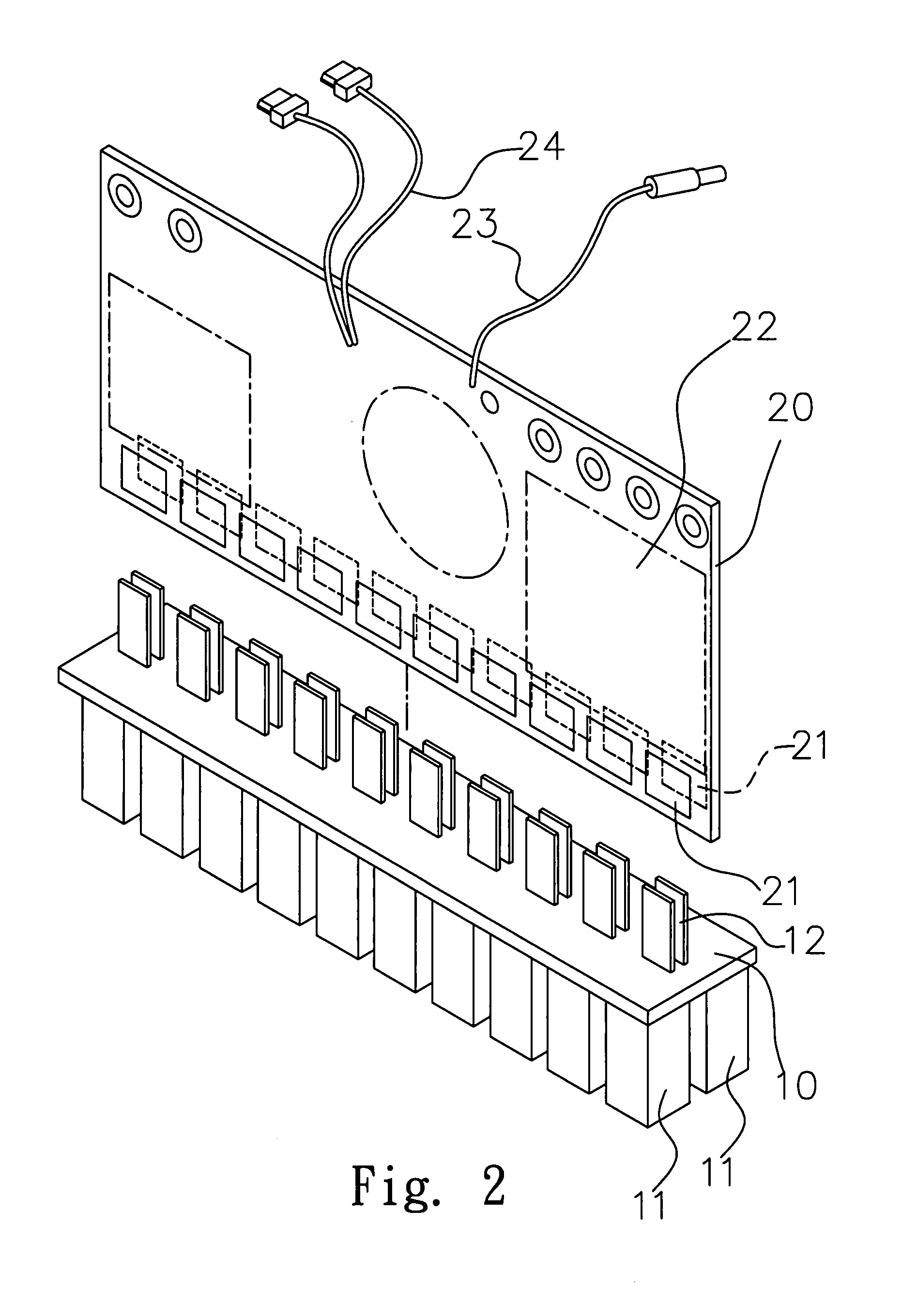
[0019]The present invention relates to a micro power supply device inserted into slots 31 of a circuit board 30, and the circuit board 30 is fixed into an electronic system. Referring to FIGS. 2 to 5, the device comprises an electric connector 10, a plurality of pins arranged in two rows 11 and disposed on a side of the electric connector 10, wherein a predetermined distance is maintained between the pins 11, and the pins 11 are sheathed with conducting plates 12, and inserted into the slots 31 of a circuit board 30 on an electronic system (as shown in FIG. 5) to constitute an electric connection.

[0020]Further, another end of the conducting plate 12 is protruded from another side of the electric connector 10, and the conducting plate 12 is installed at a position proximate to the middle of the electric connector 10, and a predetermined gap is disposed between the opposite and protruding conducting plates 12. A power supply board 20 is inserted into the gap, and the power supply boar...


PUM


Abstract

A micro power supply device is inserted into slots of a circuit board, and the circuit board is fixed into an electronic system. The device includes an electric connector and a plurality of neatly and oppositely arranged pins on a side of the electric connector, and the pins are sheathed with conducting plates, and the conducting plates are electrically connected with the slots. Another end of the conducting plates is protruded from another side of the electric connector, and a power supply board is inserted between the protruded conducting plates. The power supply board is connected with the power of an external port and other electronic equipments. The thickness of the power supply board is reduced, such that the conducting plates are centralized from both lateral side to the middle to reduce the volume of the whole electric connector, so as to reduce the volume of the whole device.

Description

BACKGROUND OF THE INVENTION[0001]1. Field of the Invention[0002]The present invention relates to a micro power supply device, and more particularly to a power supply device that centralizes all circuits on a circuit board by using a fine circuit layout to greatly reduce the volume of the power supply device.[0003]2. Description of the Related Art[0004]As science and technology advances, electronic technology is well developed accordingly, and electronic products become an indispensable part of our life. Each electronic product tends to be short, small, light and thin and comes with diversified functions, and the electronic product with the short, small, light and thin design must have densely installed electronic components to reduce their occupying space.[0005]Referring to FIG. 1 for a traditional micro power supply device, the device includes an electric connector 100, two rows of corresponding pins 101 disposed on a side of the electric connector 100 and inserted into slots (not ...

Claims


Application Information

Patent Timeline
Patent Type & Authority Applications(United States)
IPC IPC(8): H01R12/00H01R12/71H01R12/73H01R12/77
CPCH01R9/096H01R13/6658H05K1/0263H05K2201/10492H05K3/366H05K2201/10189H05K2201/10287H05K1/141H01R12/52
Inventor CHI, PEI-CHIN
Owner PORTWELL
Why Eureka
Try Eureka