Ultrasonic medical device and associated method

a medical device and ultrasonic technology, applied in the field of ultrasonic medical devices, can solve the problems of escalating costs, heavy and bulky, and ever increasing use of expensive machines and testing techniques, and achieve the effect of convenient transportation and low cos

Inactive Publication Date: 2008-09-18
WILK ULTRASOUND OF CANADA
View PDF74 Cites 149 Cited by
  • Summary
  • Abstract
  • Description
  • Claims
  • Application Information

AI Technical Summary

Benefits of technology

[0007]An object of the present invention is to provide an imaging device or system which is relatively inexpensive and easy to transport.

Problems solved by technology

One reason for the escalating costs is the ever increasing use of expensive machines and testing techniques.
Computed assisted tomography (CAT scanning), magnetic resonance imaging (MRI) and some radiological techniques have been in the forefront of contributing to mounting medical costs.
In addition to being expensive, these devices are heavy and bulky, making them ill suited to transport.
The images produced during a conventional ultrasonic scanning procedure are not easily decipherable.
Even physicians intimately familiar with internal tissue structures of human beings find it difficult to read conventional ultrasonically generated images without substantial training.
Interest in three-dimensional (3D) ultrasound imaging is increasing rapidly, notwithstanding the fact that presently, it is not possible to obtain electronic 3D volumetric data acquisition.
Such probes are not currently available, and are not expected to be in the near future due to multiplicative complexities known to those skilled in the art in implementing a 2D transducer array.

Method used


Image

  • Ultrasonic medical device and associated method
  • Ultrasonic medical device and associated method
  • Ultrasonic medical device and associated method

Examples


Embodiment Construction

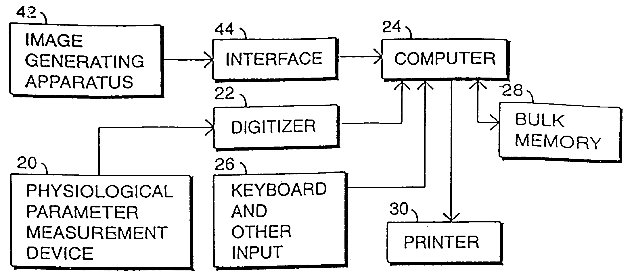
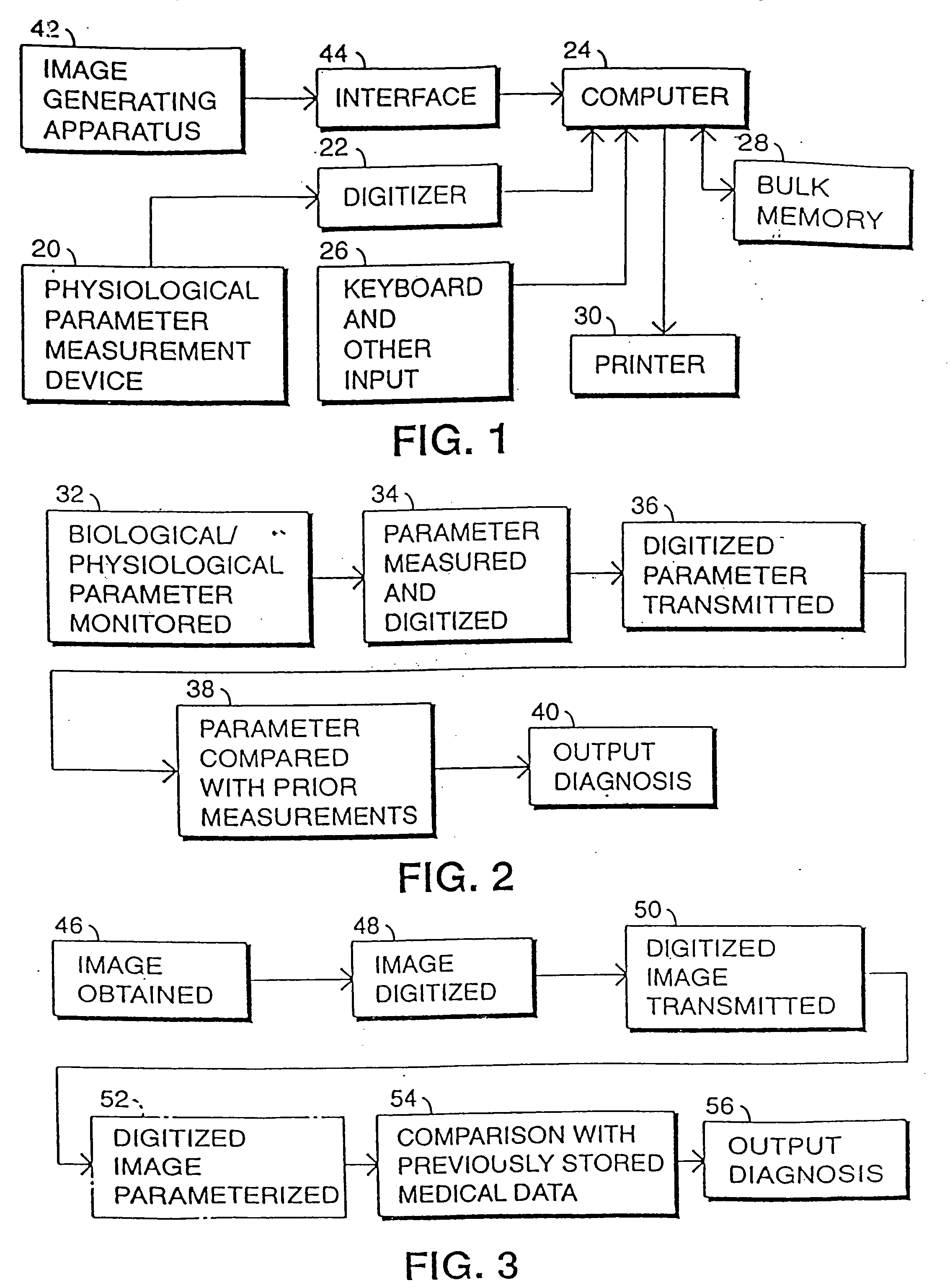
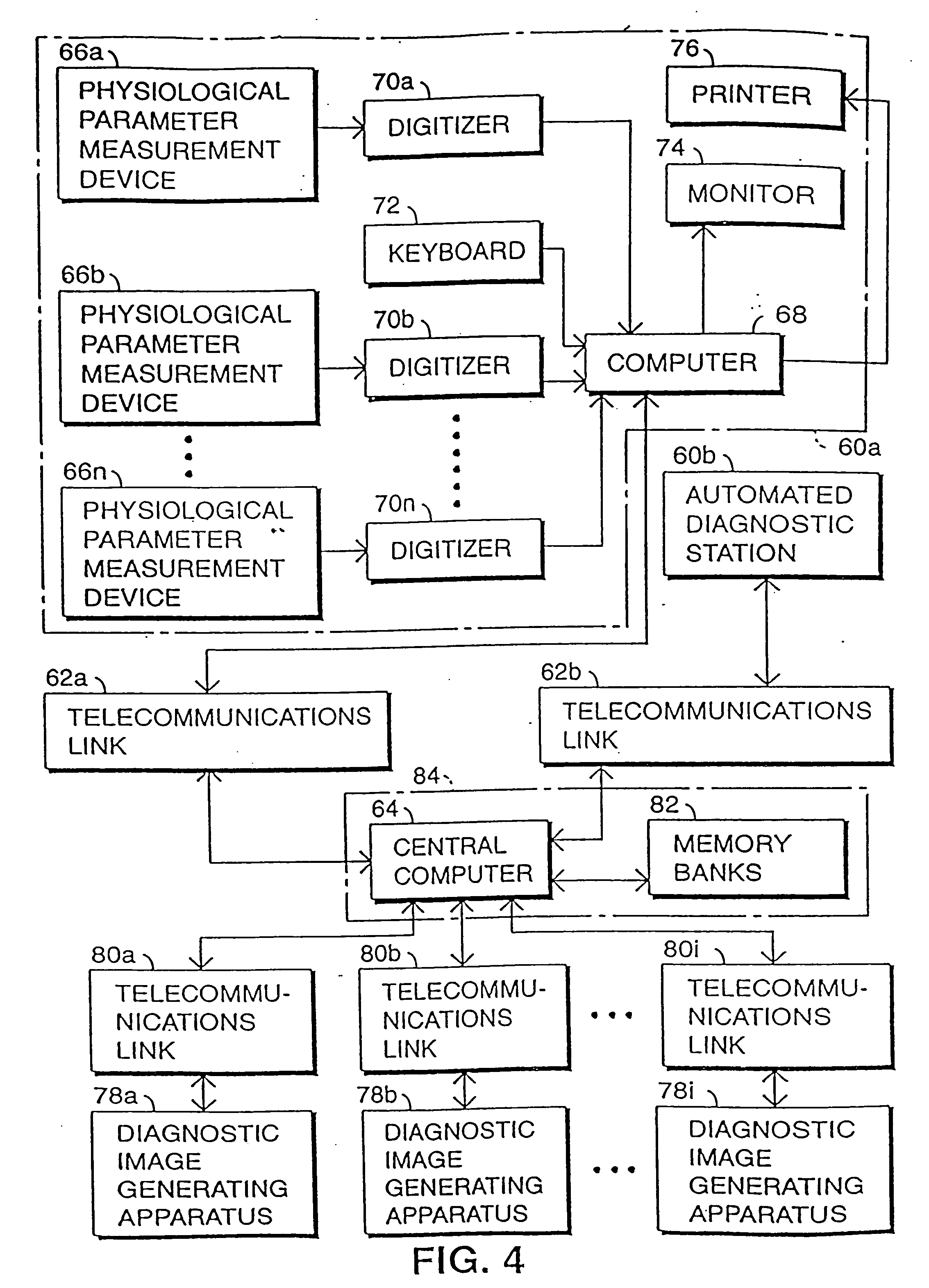
[0067]The present invention is directed chiefly to an imaging device and particularly to an ultrasonographic imaging device utilizable in diagnostic and therapeutic procedures. The ultrasonographic imaging device of the present invention is described generally hereinafter with reference to FIG. 8 et seq. The ultrasonographic imaging device, and particularly image derivation or construction portions thereof, can be employed as an image generating apparatus or scanner 42 in the medical diagnostic system of FIG. 1 or a diagnostic image generating apparatus 78a, 78b, 78i in the medical diagnostic system of FIG. 4. Alternatively or additionally, the ultrasonographic imaging device can be employed in carrying out certain minimally invasive diagnostic or therapeutic operations, examples of which are illustrated schematically in FIGS. 12 and 13.

[0068]As illustrated in FIG. 1, a medical diagnostic system comprises a device 20 for monitoring and measuring a biological or physiological paramet...


PUM


Abstract

A medical system includes a carrier and a multiplicity of electromechanical transducers mounted to the carrier, the transducers being disposable in effective pressure-wave-transmitting contact with a patient. Energization componentry is operatively connected to a first plurality of the transducers for supplying the same with electrical signals of at least one pre-established ultrasonic frequency to produce first pressure waves in the patient. A control unit is operatively connected to the energization componentry and includes an electronic analyzer operatively connected to a second plurality of the transducers for performing electronic 3D volumetric data acquisition and imaging (which includes determining three-dimensional shapes) of internal tissue structures of the patient by analyzing signals generated by the second plurality of the transducers in response to second pressure waves produced at the internal tissue structures in response to the first pressure waves. The control unit includes phased-array signal processing circuitry for effectuating an electronic scanning of the internal tissue structures which facilitates one-dimensional (vector), 2D (planar), and 3D (volume) data acquisition. The control unit further includes circuitry for defining multiple data gathering apertures and for coherently combining structural data from the respective apertures to increase spatial resolution. When the data gathering apertures are contained in a flexible web or carrier so that the instantaneous positions of the data gathering apertures are unknown, a self-cohering algorithm is used to determine their positions so that coherent aperture combining can be performed.

Description

BACKGROUND OF THE INVENTION[0001]This invention relates to a device or system for use in medical diagnoses and treatment. The device or system is especially useful for medical imaging purposes to enable a visual inspection of internal tissue structures.[0002]In recent years, the escalation of medical costs has captured substantial media and regulatory attention. One reason for the escalating costs is the ever increasing use of expensive machines and testing techniques. Computed assisted tomography (CAT scanning), magnetic resonance imaging (MRI) and some radiological techniques have been in the forefront of contributing to mounting medical costs. In addition to being expensive, these devices are heavy and bulky, making them ill suited to transport.[0003]In this age of rapidly escalating medical costs, minimally invasive operations have become the method of choice for diagnosis and treatment. In many cases, endoscopic, laparoscopic and radiographic techniques have superseded older di...

Claims


Application Information

Patent Timeline
Patent Type & Authority Applications(United States)
IPC IPC(8): A61B8/14A61B8/00A61B8/08A61B17/34A61B19/00
CPCA61B5/6804A61B8/00A61B8/08A61B8/13A61B8/4281A61B2019/5276A61B17/3403A61B19/50A61B2017/3413A61B2017/3492A61B8/483A61B8/4227A61B8/4494A61B34/10A61B2090/378Y10S128/916
Inventor WILK, PETER J.NOHARA, TIMOTHY J.WEBER, PETER T.
Owner WILK ULTRASOUND OF CANADA
Why Eureka
Try Eureka