Water retention/detention structure formed from identical panels

a technology of water retention and detention structure, which is applied in the direction of sewage draining, sewer system, construction, etc., can solve the problems of destroying habitat, contributing to storm sewer overflow, and inability to manage storm runoff water flow,

Inactive Publication Date: 2013-06-20
KRIEKEMEIER JOHN E
View PDF7 Cites 18 Cited by
  • Summary
  • Abstract
  • Description
  • Claims
  • Application Information

AI Technical Summary

Benefits of technology

[0006]The present invention provides a simple, modular, straight forward approach to a construction assembly for joining assembly panels together in a variety of different configurations for use with water retention / detention systems. In a broader context, the panels of the present invention that are particularly suitable for a water retention / detention system, may be used for a wide variety of different building and structural uses.

Problems solved by technology

Improperly managed storm runoff water flows from impervious surfaces picking up pollutants, and washes them into rivers and streams.
In addition storm water run-off causes flooding and erosion, destroys habitat, and contributes to storm sewer overflows.
Conventional retention / detention systems most often include an array of heavy and cumbersome concrete structures that are extremely expensive to transport and install.
Other water detention / retention structures consist of a multitude of small molded plastic parts that are labor intensive and often difficult to assemble due to the large number of different parts in the system.
These systems have little or no access inside the structure for maintenance, and debris removal.
Still others of these systems consist of an assemblage of large pipes or arched structures that require large quantities of expensive gravel in their installation and have very limited access for maintenance.
Therefore the teaching is limited to the creation of a square or box like structure.

Method used


Image

  • Water retention/detention structure formed from identical panels
  • Water retention/detention structure formed from identical panels
  • Water retention/detention structure formed from identical panels

Examples


Embodiment Construction

[0032]Disclosed herein are various embodiments of building panel structures and water detention / retention assemblies made therefrom. Reference will now be made in detail to the description of the embodiments as illustrated in the drawings, wherein like reference numbers indicate like parts throughout the several views.

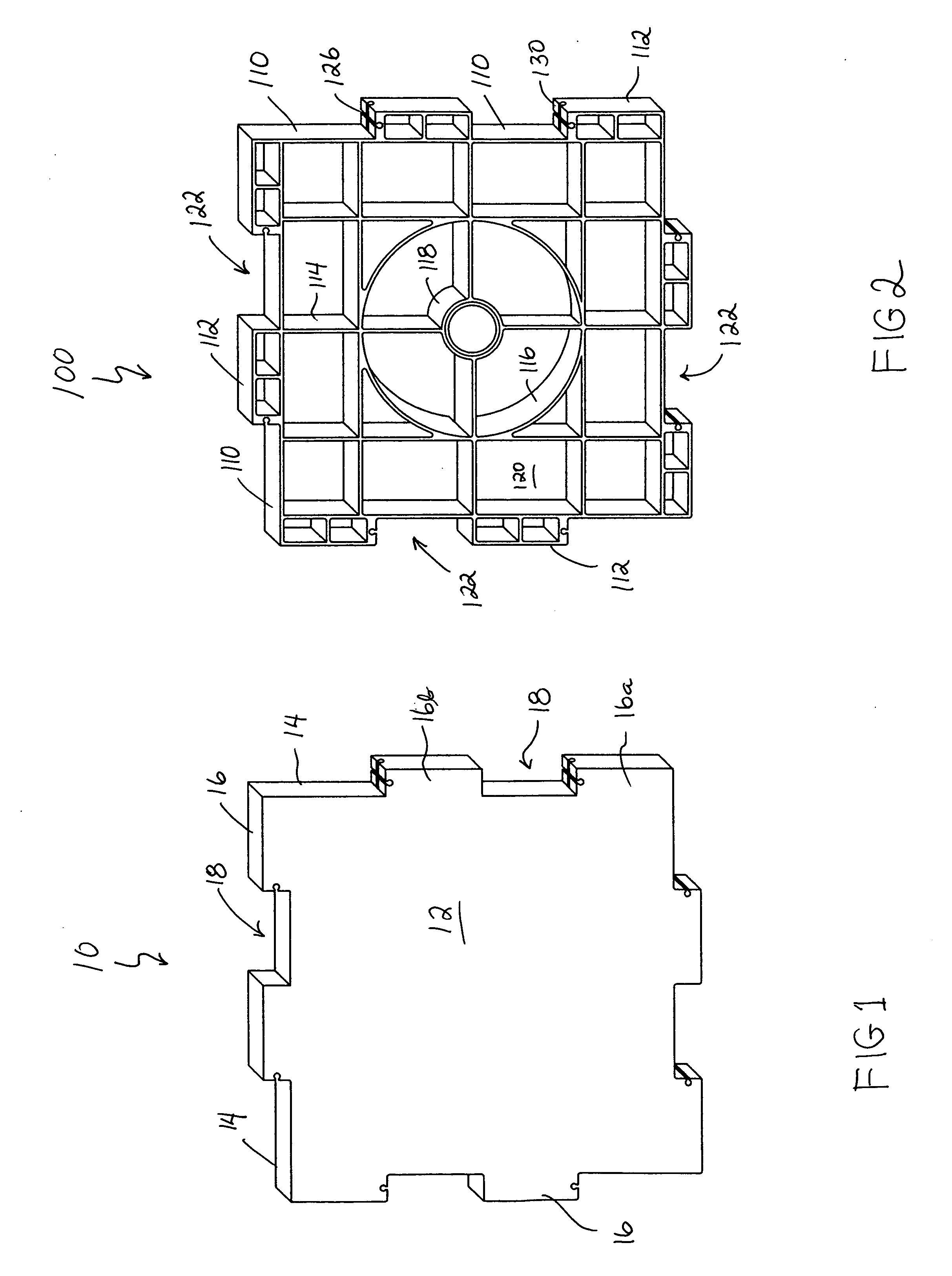
[0033]FIG. 1, illustrates a building panel 10 in accordance with the present invention. The panel 10 includes a front surface 12 and a rear surface (not shown) that is a mirror image of the front surface. The panel surface 12 is planar with side walls 14 around the periphery of the panel 10. Each side wall 14 has at least two connector tabs 16 and connector openings 18 between the tabs 16. The connector openings 18 are the same size as the tabs 16. On each side wall 14, a first one of the connector tabs 16a is located at the end of the side wall 14. A second connector tab 16b is located in a spaced relationship from the first tab 16a between the ends of the side wall 1...


PUM


Abstract

A water retention and detention assembly formed of a plurality of panels that may be interconnected edge to edge in a range of 90 through 270 degrees using a unique connector tab arrangement.

Description

REFERENCE TO RELATED APPLICATIONS[0001]This application claims the benefit of and priority to U.S. Provisional Patent Application No. 61 / 081,460 filed December Jul. 17, 2008 and U.S. patent application Ser. No. 12 / 505,233 filed Jul. 17, 2009, both entitled “Water Retention / Detention Structure Formed from Identical Panels” which is incorporated by reference in its entirety as if fully set forth herein.BACKGROUND OF THE INVENTION[0002]Improperly managed storm runoff water flows from impervious surfaces picking up pollutants, and washes them into rivers and streams. In addition storm water run-off causes flooding and erosion, destroys habitat, and contributes to storm sewer overflows. Storm water retention and detention basins can be constructed underground with reclaimed water released slowly into rivers and streams or retained on site for irrigation purposes. Properly installed underground retention structures can provide for debris and pollutant removal. Underground retention struct...

Claims


Application Information

Patent Timeline
Patent Type & Authority Applications(United States)
IPC IPC(8): E02B11/00E04B1/38
CPCE03F1/005E02B11/00
Inventor KRIEKEMEIER, JOHN E.
Owner KRIEKEMEIER JOHN E
Why Eureka
Try Eureka