
Ripper Boot

a technology of ripper and boot, which is applied in the field of ripper boot, can solve the problems of metal fatigue and fracture, considerable wear and tear, and ground up, and achieve the effects of less wear and tear, increased ripper effect, and reduced chatter and drag of the boot through the ground

Inactive Publication Date: 2008-09-25
CALDERWOOD JAMES A
View PDF17 Cites 7 Cited by
  • Summary
  • Abstract
  • Description
  • Claims
  • Application Information

AI Technical Summary

Benefits of technology

[0021]Thus, this further form of the invention provides a ripper boot whereby the ripping tooth is angled upwardly with respect to the ripper boot carrier so that the angle of attack of the ripping tooth is raised and becomes almost parallel with the ground. In altering the angle of attack in this way, it has been found that the cleaving effect of the boot is increased, chatter and drag of the boot through the ground is reduced which results in less wear and tear and less likelihood of the tooth being ripped out, as well as decreased load on the bulldozer which also reduces fuel consumption.

Problems solved by technology

The problem with having a rotatable ripping tooth is that during operation, ground up rock is able to enter into the area between the shaft of the ripping tooth and the ripper boot body.
This causes considerable wear and tear when the shaft rotates which may eventually lead to metal fatigue and fracture under extreme loads.
A further problem is that the ripping tooth tends to move and chatter during operation which is also undesirable.
Further still, where clay fines and other similar material build up in the area surrounding the ripping tooth shaft, the tooth becomes almost impossible to remove.
Existing ripper boots having rotatable teeth are also expensive to manufacture, and their use is limited to only a small range of applications.
The position of the bulldozer tyne is adjustable, however, its movement is restricted and often a desired angle of attack is not attainable.
When the tooth is ripping at too steep an angle, that is, when the angle between the longitudinal axis of the ripping tooth and the ground surface is too great, the ripper boot will begin to chatter which may result in increased wear and tear on the ripping tooth, metal fatigue and eventual fracture in the ripping tooth.
In such circumstances, the load on the bulldozer is also increased which leads to increased fuel consumption.
The nose of the ripping tooth tip may also drag when the angle is too steep, and the ripping tooth is prone to being ripped out.

Method used


Image

  • Ripper Boot
  • Ripper Boot
  • Ripper Boot

Examples


second embodiment

[0059]the invention is illustrated in FIGS. 8-9 and relates to a ripper boot 10b which has the same interference fit tooth 16 as described above, but which includes an alternate angle of attack.

[0060]This angle of attack concept can be clearly appreciated in FIG. 10 which illustrates the ripper boot 10b of the present invention, as well as a conventional ripper boot 48 in broken lines for the purpose of comparison. Those skilled in the art will appreciate that where the solid portion of the conventional ripper boot 48 extends in the same longitudinal direction as that of the carrier 14, the solid portion 26 of the ripper boot 10b is angled upwardly with respect to the carrier 14 when fully assembled. In having an upwardly angled solid portion 26, those skilled in the art will appreciate that the ripping tooth 16 once inserted will also be angled with respect to the carrier 14.

[0061]The angle of the solid portion 26 is shown in the drawings to be quite substantial for the purpose of ...

first embodiment

[0062]Existing ripper boots may be modified to include the features of ripper boot 10b. For example, a saw cut may be made at the junction between the carrier 14 and the solid portion 26 of the ripper boot 10a of the The cut would be made at a desired angle relative to the longitudinal axis of the carrier. Then, when a solid portion is welded to the angled end of the carrier 14, those skilled in the art will appreciate that it will extend at an angle corresponding with the angle of the cut.

[0063]It has been found that when the tooth is positioned at this angle, the boot cleaves through the ground more efficiently than hitherto known ripper boot arrangements resulting in similar benefits to those mentioned above including reduced chatter, reduced wear and tear on the tooth, and reduced load on the bulldozer. It is to be understood that the angle at which the solid portion 26 extends with respect to the carrier 14 may be made to vary depending on the required operation.

[0064]FIGS. 11...

third embodiment

[0065]The angle is such that in use, the ripping tooth 16 will extend slightly upwardly so as to become more parallel with the ground surface. The benefits of having a raised angle of attack as provided by this third embodiment of the invention have been described above.

[0066]Although not illustrated, it is to be understood that this ripper boot 10c could also include a retaining pin for additional support as described previously.

[0067]Ripper boot 10a could also be modified to include an angled ripping tooth according to this third embodiment by making a straight saw cut at the junction between the carrier 12 and the solid portion 26 and simply replacing the solid portion with one that has an angled bore cast there through.


PUM


Abstract

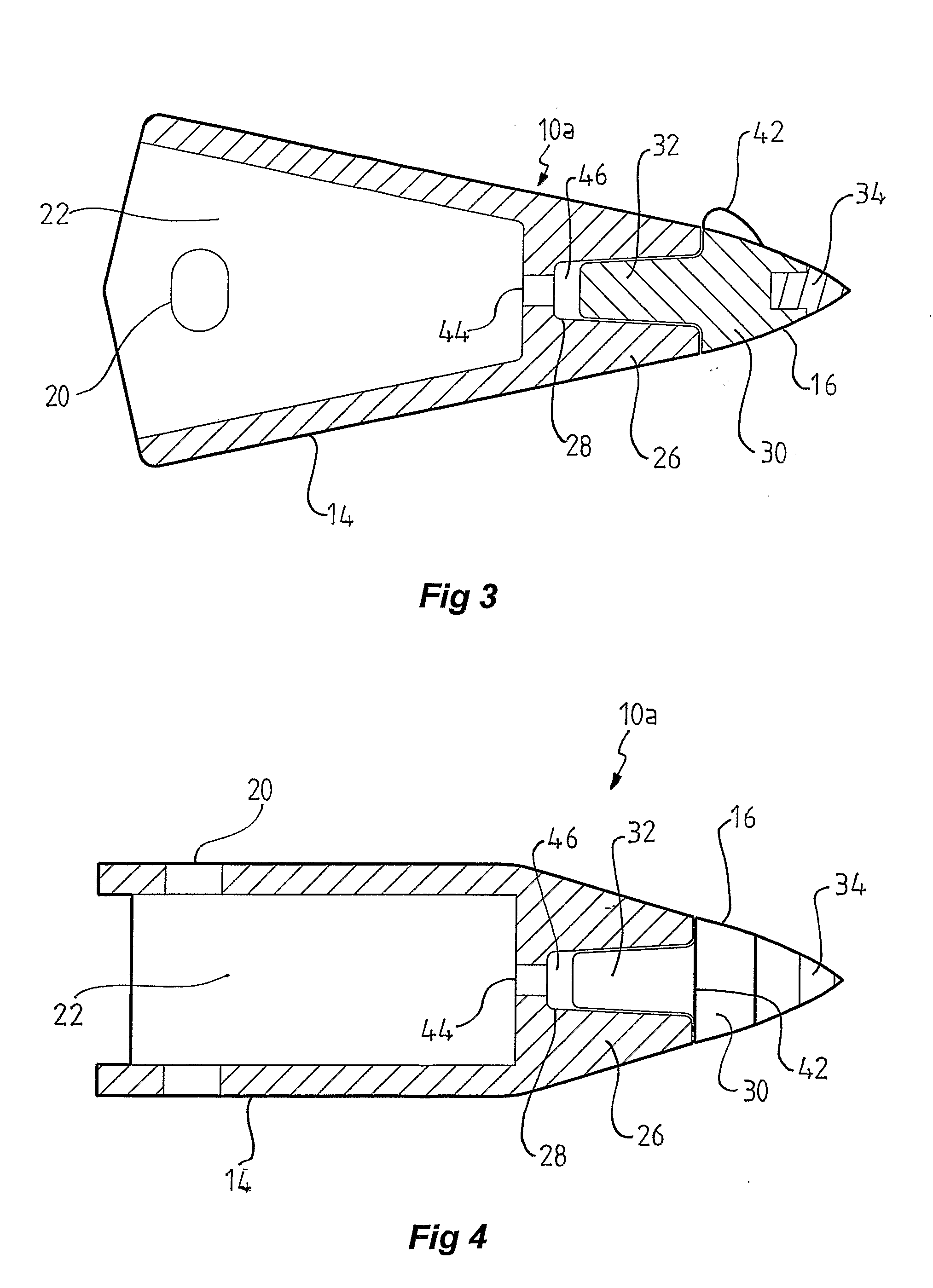
The present invention relates to improvements to ripper boots of the type adapted to be mounted to a bulldozer tyne for use in cleaving through hard ground. The ripper boot embodied in the present invention has particular application in opal mining where sometimes extremely hard ground is to be penetrated and ripped. The ripper boot includes a replaceable ripping tooth which is secured within the boot by way of an interference fit so that during use, it does not rotate. The interference fit prevents particular matter from entering between the walls of the tooth and the associated socket. In further forms of the invention, the replaceable ripping tooth is angled upwardly with respect to the carrier so that the angle of attack of the ripping tooth is raised so that it is almost parallel with the ground. The ripper boot provides a number of benefits including improved cleaving effect, reduced chatter and drag, reduced wear and tear, and reduced load on associated machinery.

Description

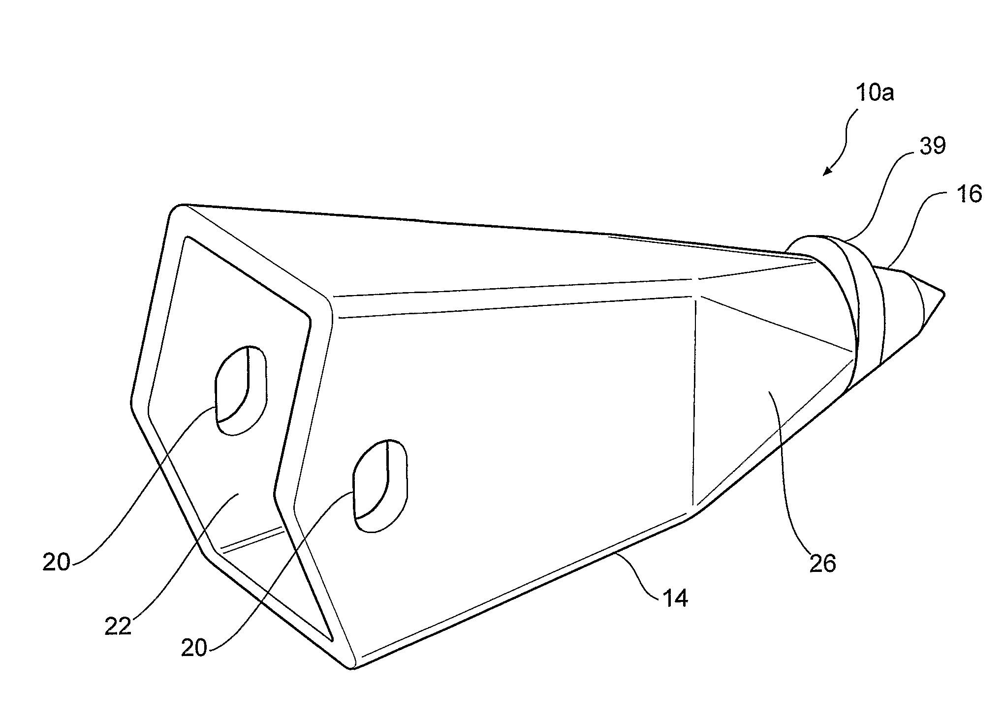
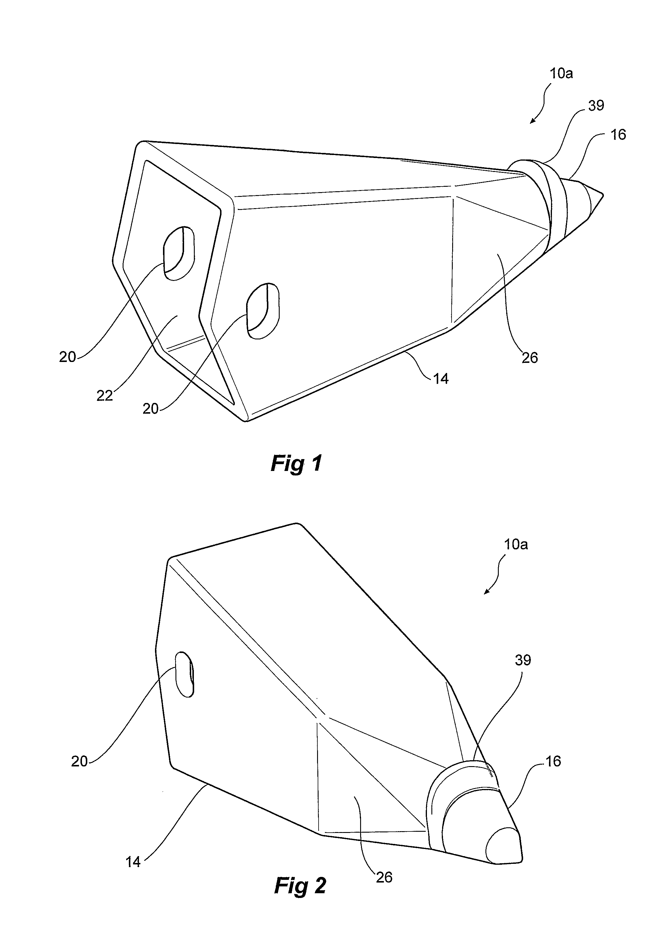
[0001]The present invention relates to an improved ripper boot and, in particular, to a ripper boot for use in a range of applications involving the ripping or cleaving of hard material. The preferred application of the present invention is in opal mining where hard ground is to be penetrated in an attempt to locate opal.BACKGROUND OF THE INVENTION[0002]Ripper boots are typically used where extremely hard rock or compacted soil is encountered and is required to be penetrated and ripped in an attempt to locate and extract precious stones such as opal. The ripper boot includes a carrier which is typically secured to a bulldozer tyne and a ripping tooth section secured to the nose of the carrier to rip through rock, typically to a depth of approximately 300 mm at a time. In the case of opal mining, the loosened rock is then pushed away, while spotters check for signs of opal. The ripping tooth can also be replaceable. The present inventor has identified some problems with such conventi...

Claims


Application Information

Patent Timeline
IPC IPC(8): E02F9/28
CPCE02F5/32E02F9/285E02F3/80E02F9/2875E02F9/28
Inventor CALDERWOOD, JAMES A.
Owner CALDERWOOD JAMES A
Learn More