
Aseismic joint

a technology of seismic joints and joints, applied in the direction of couplings, vibration dampers, building components, etc., can solve the problems of structural elements, oscillations are subject to cracking, permanent damage or even structural yielding, and users who have to opera

Inactive Publication Date: 2008-09-25
KIVATEC
View PDF7 Cites 3 Cited by
  • Summary
  • Abstract
  • Description
  • Claims
  • Application Information

AI Technical Summary

Benefits of technology

"The present invention is an aseismic joint that has specific features. These features help to achieve the stated goals of the invention. The technical effects of this invention are improved performance and efficiency in reducing seismic activity and its associated risks."

Problems solved by technology

Due to the low elasticity shown, these structural elements when submitted to vibratory phenomena and in particular low-frequency and medium-high-amplitude oscillations are subjected to cracking, permanent damages or even structural yielding.
Said gaps give rise to even important size discontinuities between the different structural elements of the building that can cause risks to users who have to operate or move in close proximity to these discontinuities.
In fact, in the event of strong misalignments between the two structural elements, which are characteristic of seismic phenomena, the bars would be submitted to an excessive inclination which would lead them to interfere with the guides defining said grooves and to impact on same.
In addition, due to the covering element resting on a limited number of bars, the covering element may be unsuitable for supporting high loads or being used for going over gaps having important sizes.
A further drawback is given by the necessity to take into account expensive working operations for manufacturing the ball-shaped ends of the bars and the grooves of circular cross section.
In addition, a joint of the above described type is unsuitable for creating a waterproofing effect between the gap and the space overlying the joint.
In fact the covering element merely slidably resting on the two structural elements does not prevent leakage of fluids, in particular liquids, towards the gap, and therefore the structure of the joint resulting therefrom is not suitable for being correctly used in buildings for civil use or habitation where adjacent or superposed spaces are to be isolated from each other.

Method used


Image

  • Aseismic joint
  • Aseismic joint
  • Aseismic joint

Examples


first embodiment

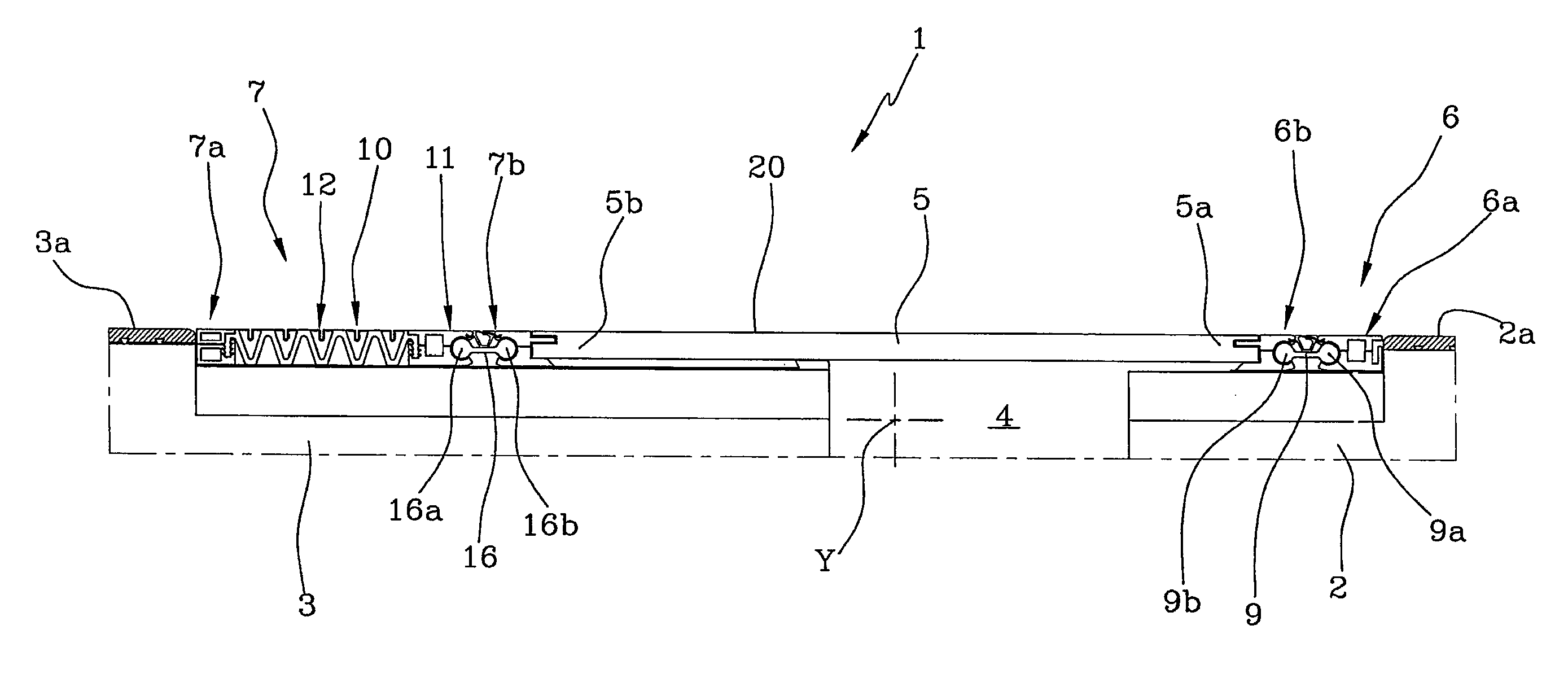
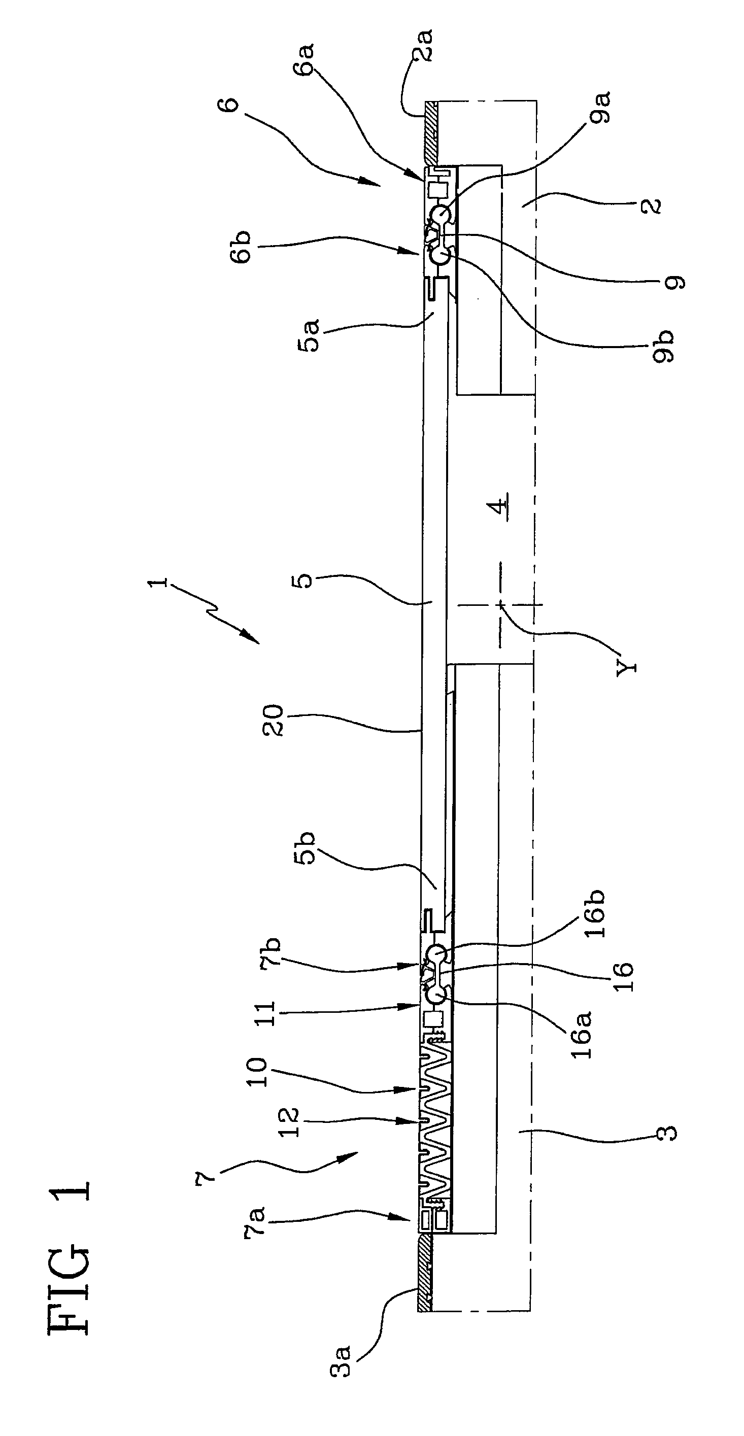
[0060]According to the invention shown in FIG. 3, the movable element 11 is directly connected, preferably in a stiff manner, to the second end 5b of the covering element 5. Under this circumstance, possible oscillating movements of the covering element 5 relative to the second anchoring portion 7a, and therefore to the second structural element 3, are allowed due to deformability of the concertina-shaped element 12 that is able to bear bending deformations of its own at least at an end thereof connected to the movable element 11. In particular, the concertina-shaped element 12 has a curved end 12e which is insertable by friction fit into a corresponding seat of the movable element 11.

second embodiment

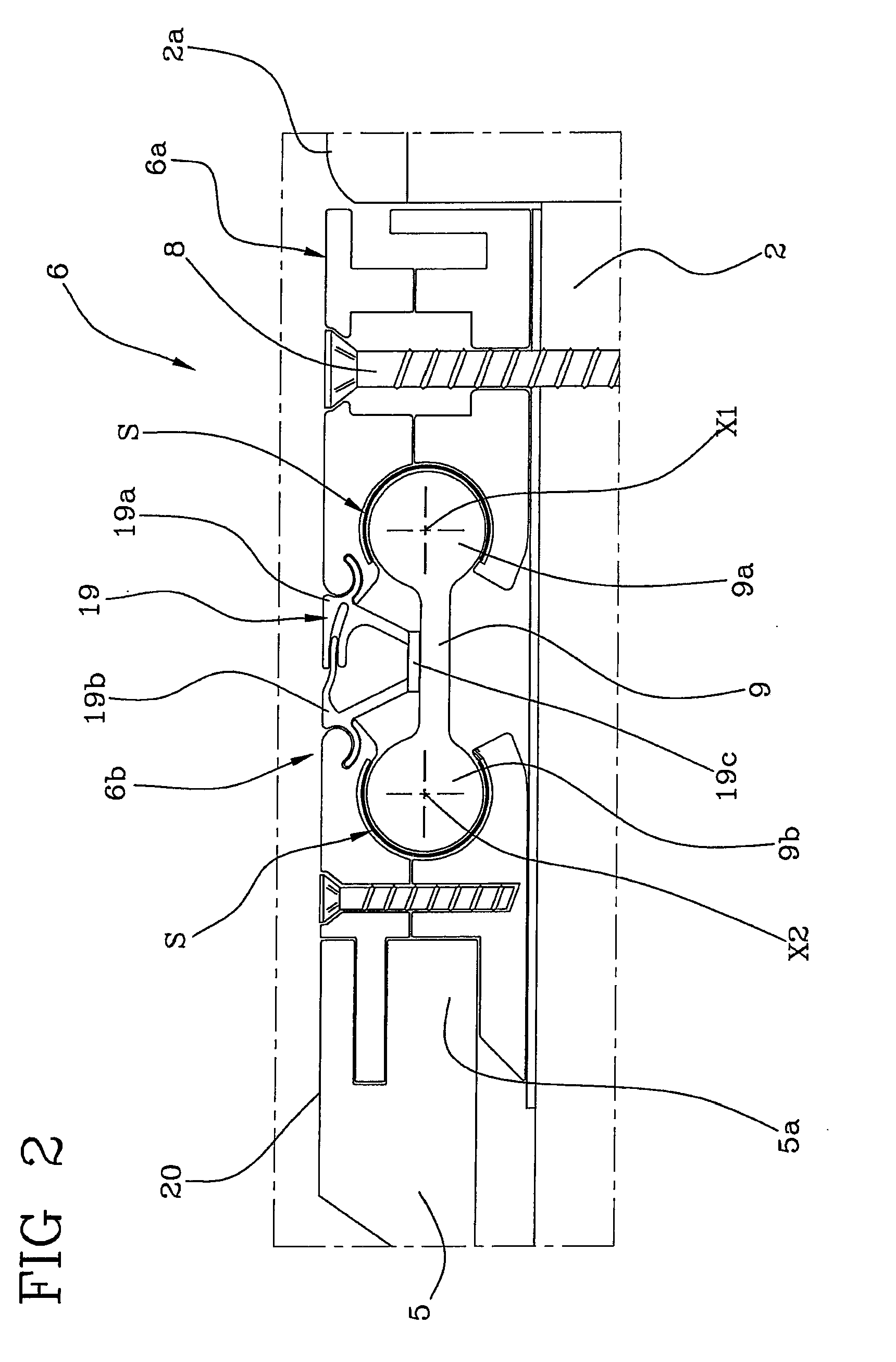
[0061]In accordance with the invention, shown in FIG. 4, the second interconnecting portion 7b comprises a second connecting-rod element 16 operatively acting between the movable element 11 and the second end 5b of the covering element 5 to allow relative rotations between the latter, even of high extent.

[0062]In accordance with the view in FIG. 4, the second connecting-rod element 16 has a first end 16a hinged on the movable element 11, and a second end 16b, opposite to the first one 16a, hinged on the second end 5b of the covering element 5. Said first 16a and second 16b ends of the second connecting-rod element 16 therefore define as many connecting hinges between the second connecting-rod element 16 and the movable element 11 and second end 5a of the covering element 5, respectively.

[0063]Under this circumstance, the first 16a and second 16b ends of the second connecting-rod element 16 rotate around a third “X3” and a fourth “X4” rotation axis respectively, which axes are differ...


PUM


Abstract

A seismic joint, for covering a gap (4) defined between a first (2) and a second (3) structural element, comprises: a first anchoring portion (6a) to be steadily associated with the first structural element (2); a first interconnecting portion (6b) rotatably connected to the first anchoring portion (6a); a covering element (5) having a first end (5a) rotatably in engagement with the interconnecting element (6b) and a second end (5b) able to be engaged in a slidably supported relationship on the second structural element (3).

Description

FIELD AND BACKGROUND OF THE INVENTION[0001]The present invention relates to an aseismic joint, and applies to the sector of building constructions adapted to withstand seismicphenomena.[0002]In more detail, the invention relates to a joint used for connecting the structural elements of a building such as floors, slabs, or more generally masonry works to each other, in such a manner that a structural continuity is ensured between the structural elements themselves on occurrence of stresses transmitted to the building by seismic phenomena.[0003]It is to be pointed out that structural elements in constructing aseismic buildings cannot be rigidly connected to each other. It is in fact known that structural elements are made of materials with a weak elasticity such as bricks and tiles, concrete, reinforced concrete. Due to the low elasticity shown, these structural elements when submitted to vibratory phenomena and in particular low-frequency and medium-high-amplitude oscillations are su...

Claims


Application Information

Patent Timeline
Patent Type & Authority Applications(United States)
IPC IPC(8): E04B1/98E04H9/02F16F7/12
CPCE01D19/06Y10T403/45E04H9/021E04B1/681
Inventor TORSANI, DAVIDE
Owner KIVATEC
Learn More