Sealer Gun

a technology of sealing gun and sealer, which is applied in the field of sealing gun, can solve the problems of difficult uniform application for even an expert, and achieve the effects of reducing the difficulty of even an expert to apply uniform amount, reducing the difficulty of sealing gun cutting at the final stage of application, and reducing the difficulty of sealing gun wear

Inactive Publication Date: 2008-09-25
HONDA MOTOR CO LTD +1
View PDF3 Cites 10 Cited by
  • Summary
  • Abstract
  • Description
  • Claims
  • Application Information

AI Technical Summary

Benefits of technology

[0016]According to the present invention, with the provision of the controlling member for controlling the moving-backward strokes of the needle valve in a regulated manner, and the tapered portion at the tip of the needle valve, it is possible to control a drastic increase of the spout amount at the time of starting to pull the trigger, and it is also possible to adjust the position of the needle valve in a regulated manner from a position for a large bead width to a position for a small bead width in a state where the trigger is pulled to the maximum. Consequently, it is possible to conduct uniform application in a predetermined bead width irrespective of the skill of an operator such as fine adjustment of the trigger operation amount, adjustment of the moving velocity of the sealer gun, or the like.
[0017]With the provision of the tapered portion, it is possible to control a drastic increase of the spout amount at the time of starting to pull the trigger. In addition, with the provision of the ball portion to be brought into contact or be separated from the valve seat at the back of the tapered portion, it is possible to block the hole of the valve seat quickly. Consequently, cut of the sealer at the final stage of the application can be improved, and thereby the sealer can be prevented from being left in a state of string. Also, in the case of the tapered portion alone, since the tapered portion repeatedly moves while rubbing against the hole of the valve seat, the valve seat and the tapered portion are easily worn out. However, with the provision of the ball portion, wear-out of the needle valve can be delayed, and thus the sealer can be prevented from leaking out due to wear-out of the needle valve.
[0018]FIG. 1 is a cross-sectional view of a sealer gun according to the present invention;
[0019]FIG. 2 is a cross-sectional view taken along line A-A of FIG. 1;
[0020]FIG. 3 is an exploded perspective view of a notch portion; and
[0021]FIG. 4 is an enlarged view of a ball portion provided at the tip of a needle valve.

Problems solved by technology

However, it is extremely difficult for even an expert to apply a uniform amount by adjusting the degree of the trigger operation in the course of the application.

Method used


Image

  • Sealer Gun
  • Sealer Gun
  • Sealer Gun

Examples


Embodiment Construction

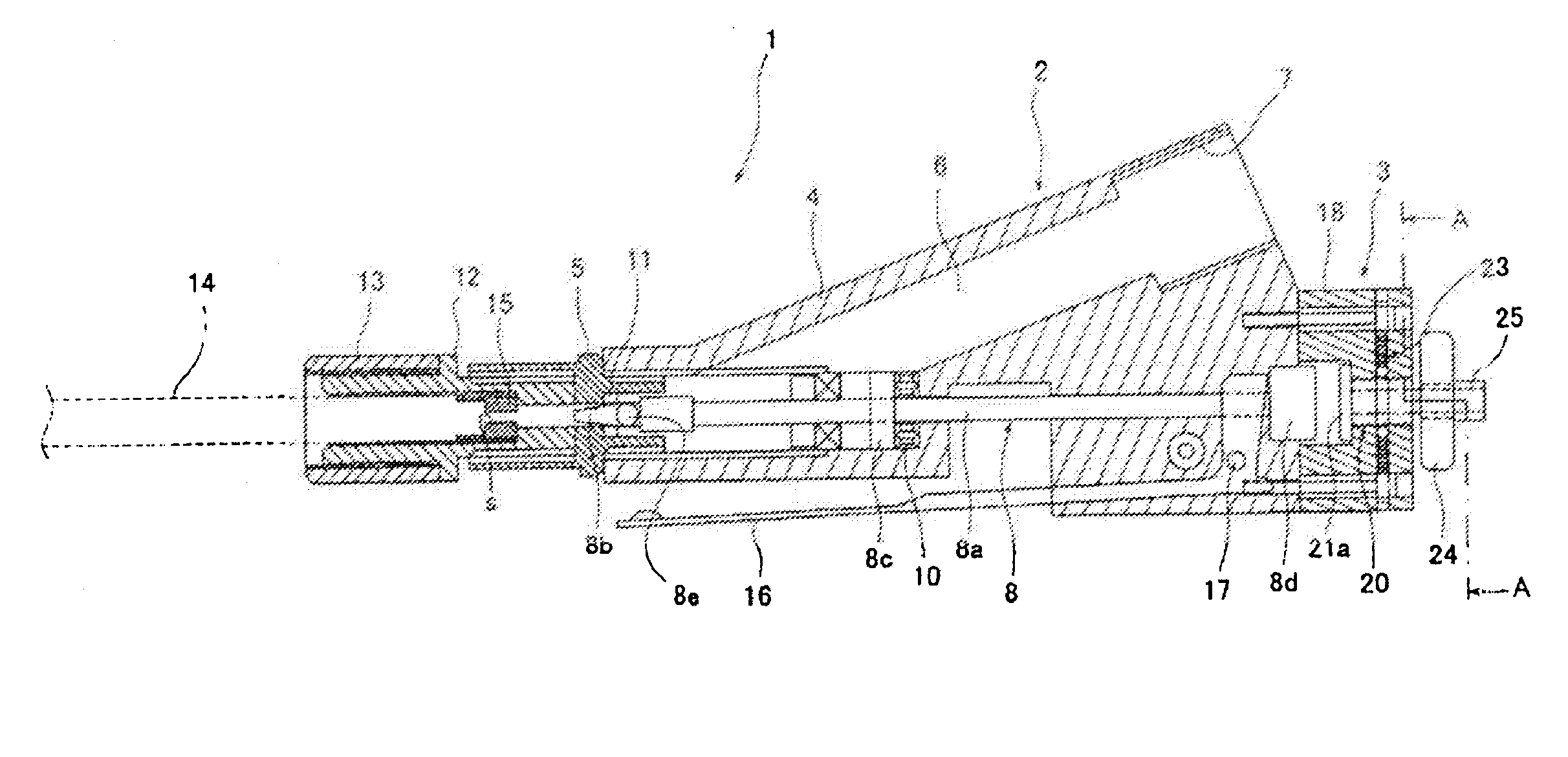
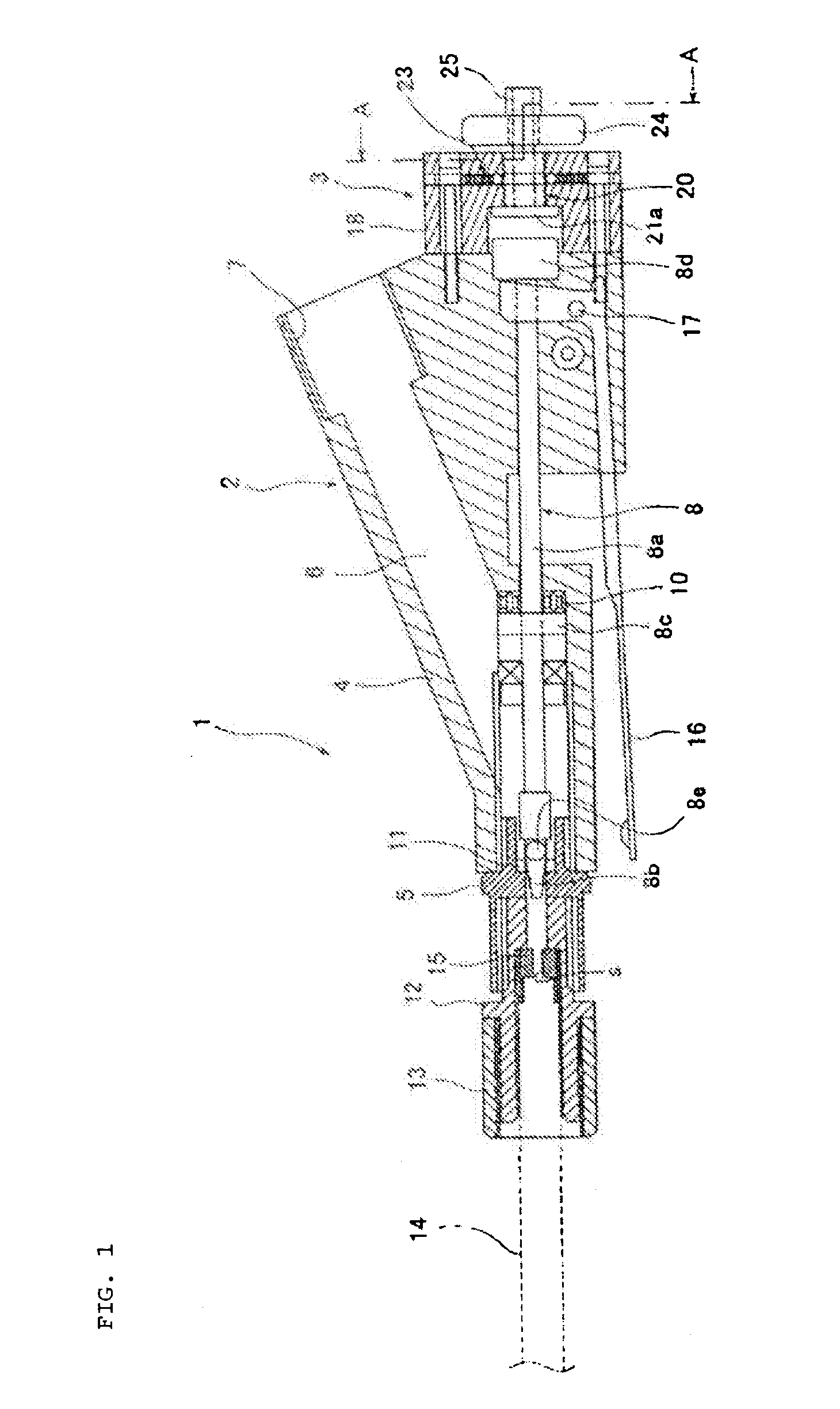
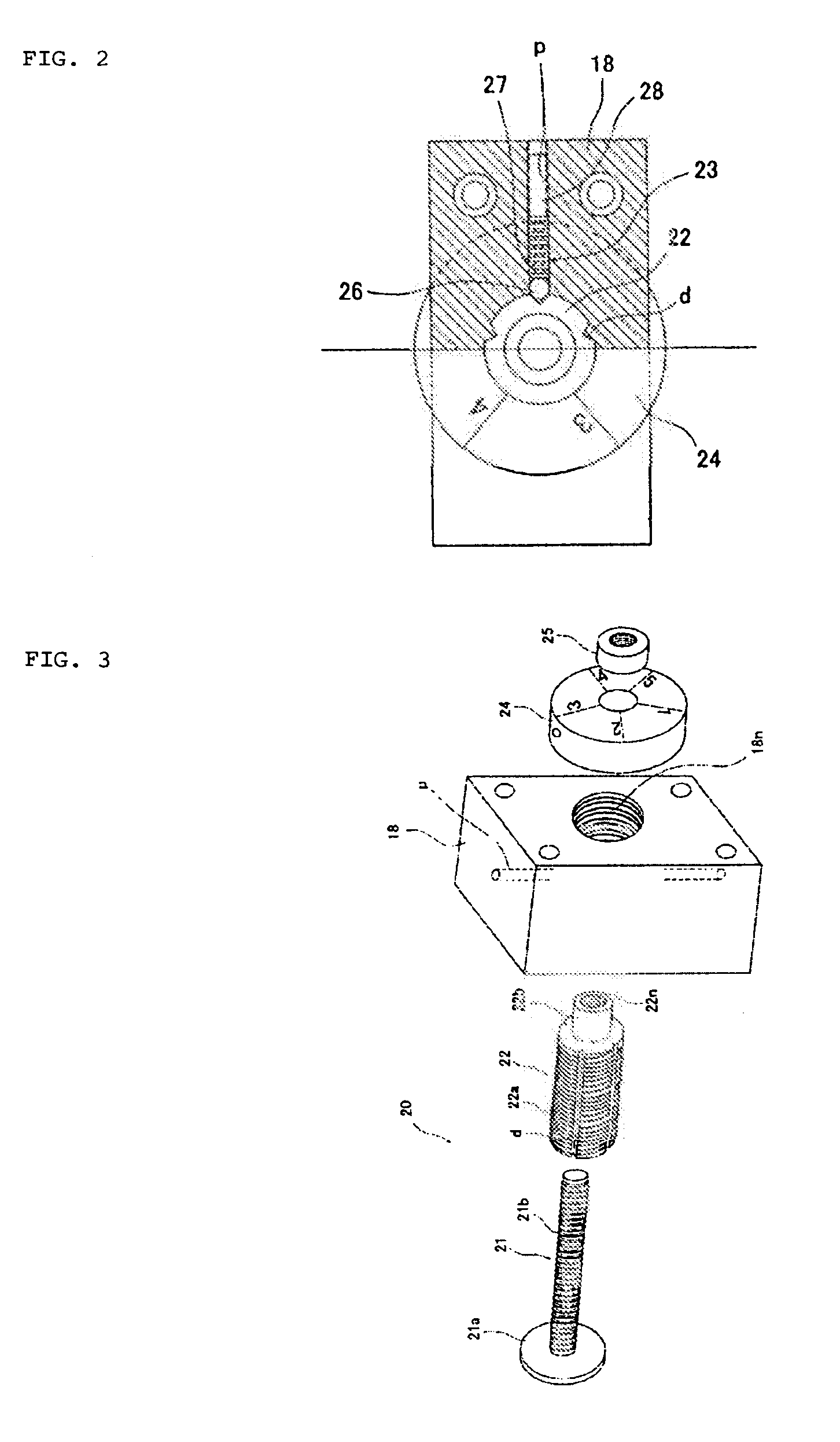
[0022]Preferred embodiments of the present invention will now be described with reference to the accompanying drawings. FIG. 1 is a cross-sectional view of a sealer gun according to the present invention, FIG. 2 is a cross-sectional view taken along line A-A of FIG. 1, FIG. 3 is an exploded perspective view of a notch portion, and FIG. 4 is an enlarged view of a ball portion provided at the tip of a needle valve.

[0023]According to a sealer gun 1 of the present invention, even an operator having no expert skill can set a bead width of an applied sealer to be a desired one, and conduct uniform application from the initial stage to the final stage. As shown in FIG. 1, the sealer gun 1 comprises a gun body 2, and a notch portion 3 which is a controlling member.

[0024]The substantially central portion of the gun body 2 forms a grip portion 4. A nozzle 5 is provided at the tip of the gun body 2, and a sealer feeding passage 6 is connected to the nozzle 5. A connecting portion 7 to which a ...


PUM


Abstract

The object of the present invention is to provide a sealer gun in which even an operator having no expert skill can easily conduct application by optionally setting the bead width, and keep the application uniform from the initial stage to the final stage. In the sealer gun, the needle valve is moved backward by predetermined strokes by operating the trigger, and a sealer is spouted from the gap between the valve seat and the needle valve. In this instance, with the adjusting knob of the notch portion provided in the base portion of the gun body, the position-adjusting member is moved back and forth, and the moving-backward stroke of the needle valve is controlled. The tapered portion 8b is formed at the tip of the needle valve, and the orifice member is provided in the sealer passage in the downstream of the valve seat so as to absorb the pulsating pressure variation of the sealer.

Description

TECHNICAL FIELD [0001]The present invention relates to a sealer gun for applying a viscous material such as a sealing material or a tackiness agent in which a bead width (application width) can be set optionally and uniform application can be achieved.BACKGROUND ART [0002]Conventionally, a sealer is applied to a joint section of, for example, a panel for a vehicle so as to keep airtight and watertight properties and prevent rusting at the same time. In operation, while a sealer stored in a tank or the like is introduced to a sealer gun by a pumping means such as a pump, a needle valve of the sealer gun is moved backward by a trigger operation so as to form a gap between the needle valve and the valve seat, and thereby the sealer is spouted from the gap. The sealer is applied to an object in a bead state by moving the sealer gun. In the sealer gun, there is a difference between the initial spout amount at the time of starting the application of the sealing material and the spout amou...

Claims


Application Information

Patent Timeline
Patent Type & Authority Applications(United States)
IPC IPC(8): B05C5/00B05B1/30B05C11/10E04F21/165
CPCB05B1/3046E04F21/165B05C11/1034B05C5/00
Inventor HIRATA, KOUTAROUKOKUBU, SOUICHI
Owner HONDA MOTOR CO LTD
Why Eureka
Try Eureka