Fuel Hose
Active Publication Date: 2008-09-25
TOKAI RUBBER IND LTD
View PDF12 Cites 9 Cited by
- Summary
- Abstract
- Description
- Claims
- Application Information
AI Technical Summary
Benefits of technology
[0058]According to the present invention, when the fuel hose or the filler hose is fitted on a mating pipe and an end portion of the hose is tightened by a hose clamp, an inner peripheral surface of the end portion of the hose can be clamped on an outer peripheral surface of the mating pipe in close contact with each other under uniform and required surface pressure throughout an entire circumference thereof, and desired sealing performance can be ensured.
[0059]In the present invention, since the outer rubber layer is formed from a soft rubber material that has a low rubber hardness and a high deformability, or the outer rubber layer may be formed from a soft rubber material that has a low rubber hardness and a high deformabilit
Problems solved by technology
However, such typical rubber hose cannot sufficiently meet to requirements for low permeability to fuel, which increase more and more recently.
However, the resin barrier layer is hard since resin is a material harder than rubber.
So, in a filler hose including the resin barrier layer laminated on an inner side of the outer rubber layer to an axial end of the hose, when the filler hose is fitted on a mating pipe, sealing performance are insufficient due to poor contact between the mating pipe and the resin barrier layer that defines an inner surface of the hose.
And, since the resin barrier layer defining the inner surface of the filler hose is hard and exhibits a large deformation resistance during fitting of the filler hose on the mating pipe, a great force is required for fitting or slipping the filler hose on t
Method used
View moreImage
Smart ImageViewing Examples

Examples
 PUM
| Property | Measurement | Unit |
|---|---|---|
| Angle | aaaaa | aaaaa |
| Angle | aaaaa | aaaaa |
| Angle | aaaaa | aaaaa |
Abstract
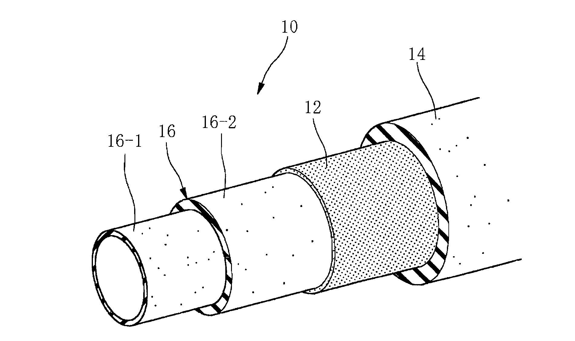
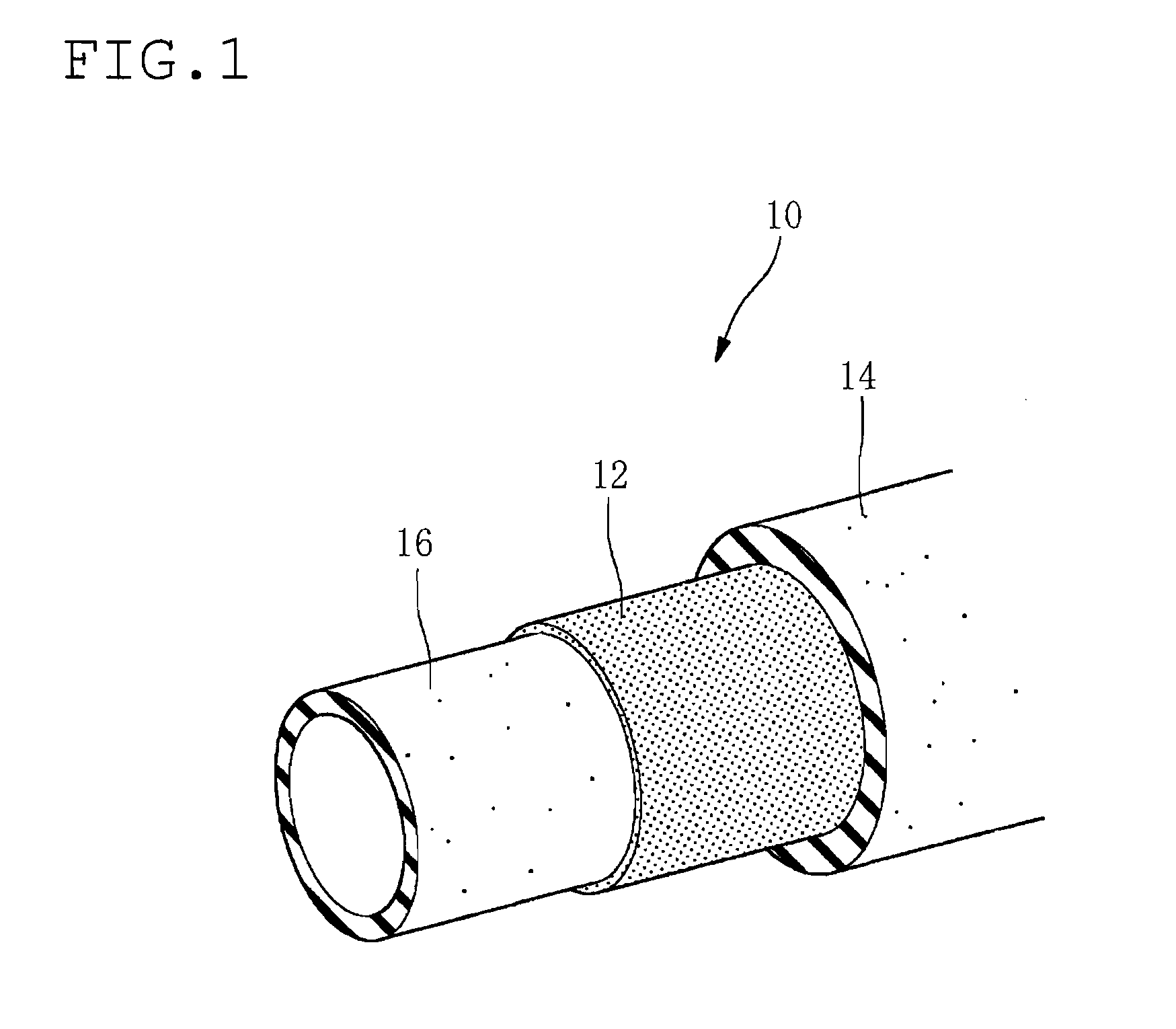
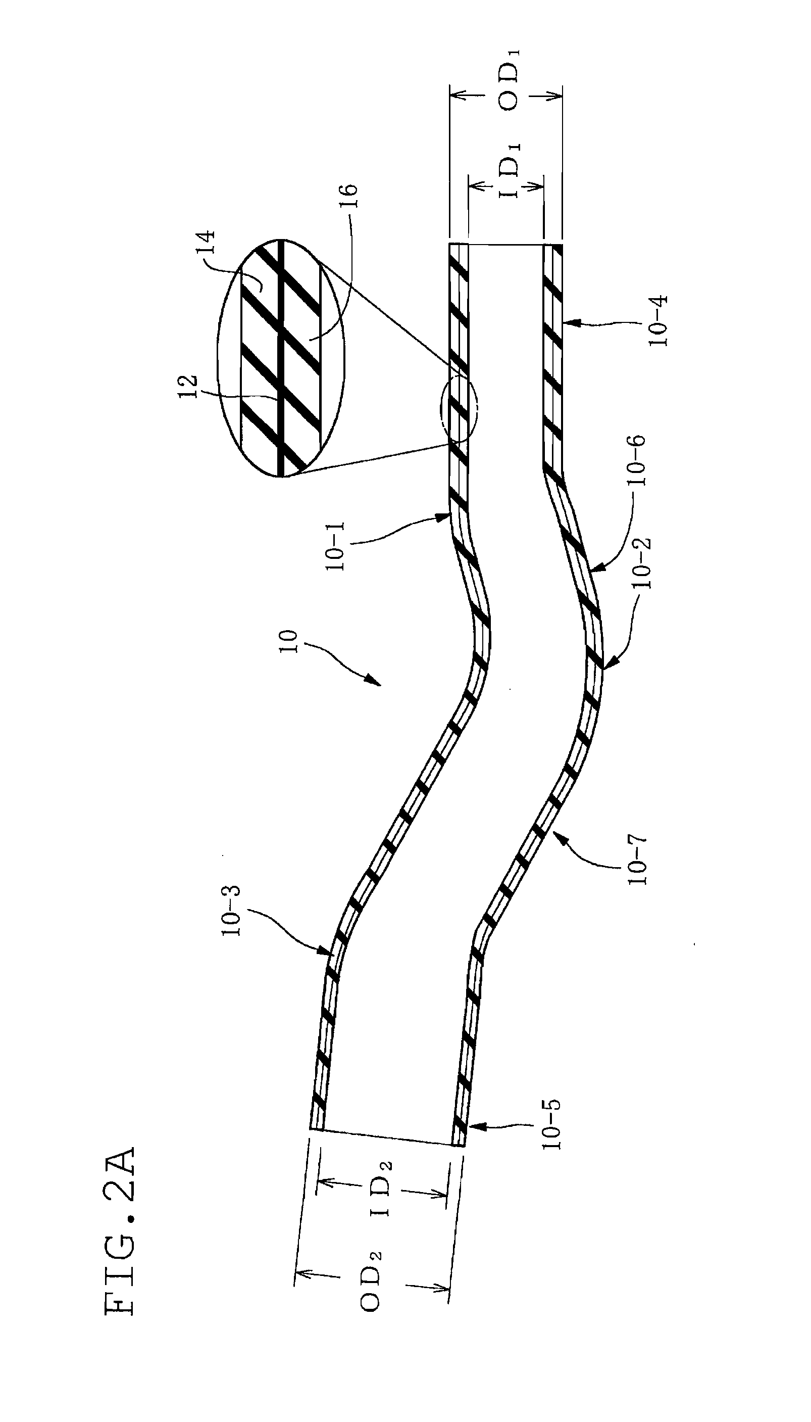
A fuel hose for a fuel pipeline in an motor vehicle has a multilayer structure including a resin barrier layer having low permeability to fuel, an outer rubber layer laminated on an outer side of the barrier layer and an inner rubber layer laminated on an inner side of the barrier layer and defining an inner surface layer of the fuel hose. The multilayer structure is formed throughout an entire length of the fuel hose. A rubber hardness of the inner rubber layer is higher than a rubber hardness of the outer rubber layer.
Description
BACKGROUND OF THE INVENTION[0001]1. Field of the Invention[0002]The present invention relates to a fuel hose that includes a resin barrier layer having low permeability to fuel in a middle in a radial direction or in a cross-section thereof and transports a fuel, for example, a filler hose of a resin-rubber composite for transporting a fuel to a fuel tank.[0003]2. Description of the Related Art[0004]In a filler hose adapted for transporting a fuel injected in a fuel inlet to a fuel tank in a motor vehicle, a typical rubber hose made of a blend of acrylonitrile-butadiene rubber and polyvinyl chloride (NBR / PVC blend, NBR+PVC) or the like has been conventionally used. Such rubber hose of NBR+PVC has a high vibration-absorbability, easiness of assembly, and a relatively excellent low permeability to fuel (gasoline).[0005]However, such typical rubber hose cannot sufficiently meet to requirements for low permeability to fuel, which increase more and more recently.[0006]As a countermeasure...
Claims
Login to view more Application Information
Patent Timeline
 IPC IPC(8): F16L11/04F16L11/12
CPCB32B1/08B32B25/04Y10T428/1393F16L2011/047F16L11/04
Inventor SAKAZAKI, KAZUSHIGESUGITA, KENTARO
Owner TOKAI RUBBER IND LTD
- R&D Engineer
- R&D Manager
- IP Professional
Why Eureka
- Industry Leading Data Capabilities
- Powerful AI technology
- Patent DNA Extraction
Try Eureka
Browse by: Latest US Patents, China's latest patents, Technical Efficacy Thesaurus, Application Domain, Technology Topic.
© 2024 PatSnap. All rights reserved.Legal|Privacy policy|Modern Slavery Act Transparency Statement|Sitemap