Supercharge Your Innovation With Domain-Expert AI Agents!

Proppant suspension testing devices and methods of use

a technology of suspension testing and proppant, which is applied in the direction of survey, instruments, borehole/well accessories, etc., can solve the problems of crosslink fracturing fluids, difficult to measure elasticity, and difficult to meet the needs of fracturing rheologists

Inactive Publication Date: 2008-09-25
HALLIBURTON ENERGY SERVICES INC
View PDF4 Cites 12 Cited by
  • Summary
  • Abstract
  • Description
  • Claims
  • Application Information

AI Technical Summary

Problems solved by technology

Instruments such as Fann Model 50 viscometers are available for measuring viscosity, including at high temperatures and pressures, but elasticity is much more elusive to measure.
In laboratory research, sample volume is often very limited, thus necessitating rheological testing and evaluation of small quantities.
Where viscous drag dominates, as in the classical case of a tow-winged vertical fracture with parallel-plate geometry, the challenge in proppant transport is to ensure that vertical settling time is much greater than horizontal travel time.
The complex viscoelastic nature of crosslink fracturing fluids presents a dilemma for the fracturing rheologist.
However, the actual fracturing process involves large amounts of shear strain of multiple orders of magnitude, well beyond the linear elastic range.
However, the Model 50 and most other bench-top viscometers / rheometers are not adequately equipped to handle proppant-laden fluids.
In the case of concentric cylinders, the centrifugal forces tend to stratify the particles, thus resulting in nonrelevant data.
In cone-plate and plate-plate viscometers, the small gaps necessary to provide torque sensitivities result in “particle jamming.” Additionally, the large density differences between most proppants and conventional fracturing fluids can result in settling during testing, thus producing unreliable results.
Un-crosslinked well fluids are not designed to support proppant and attempts to test with conventional equipment results in errors due to proppant settling or fallout.
For example, conventional viscometers and rheometers, are not capable of accepting fluids with particulates the size of proppants, ranging from a few hundred microns to 1,000 microns.
In the cases in which “large gap devices” have been employed to solve this problem, centrifugal forces and local vortices cause significant error due to sample stratification of the proppant.
On the other hand, conventional testing devices that provide constant agitation do not prevent the particle settling, and may operate in the turbulent regime.

Method used


Image

  • Proppant suspension testing devices and methods of use
  • Proppant suspension testing devices and methods of use
  • Proppant suspension testing devices and methods of use

Examples


Embodiment Construction

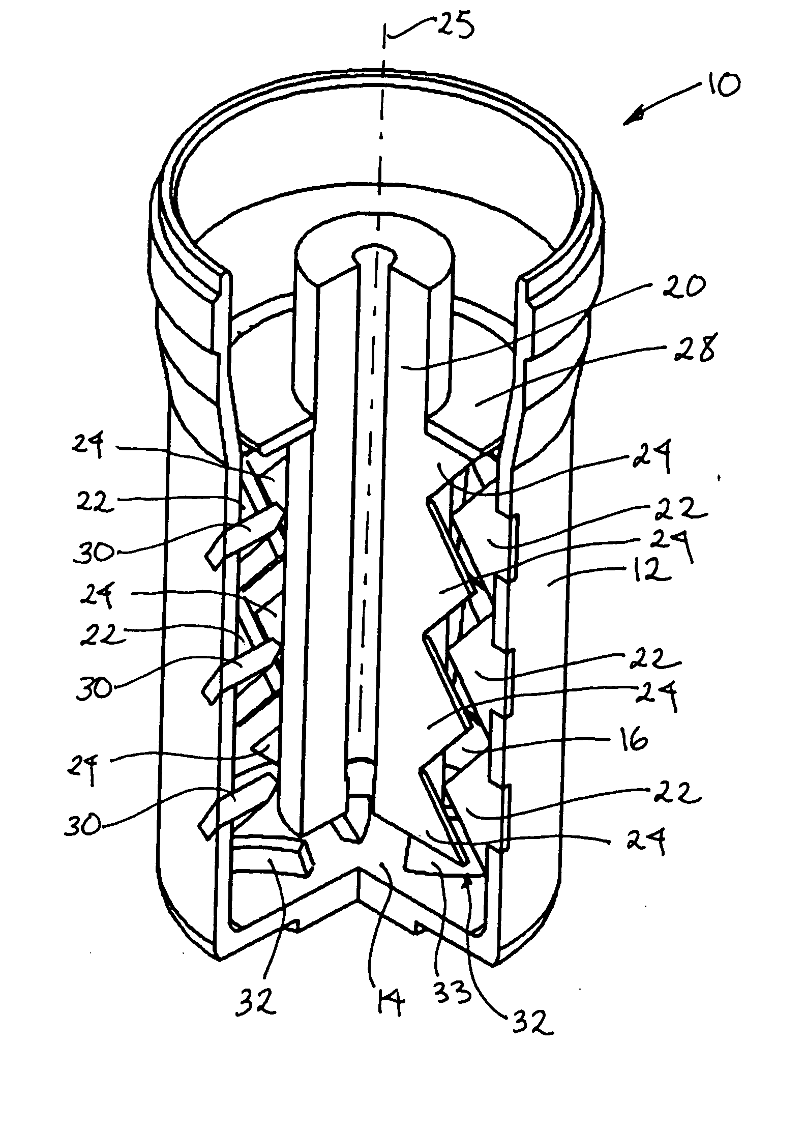
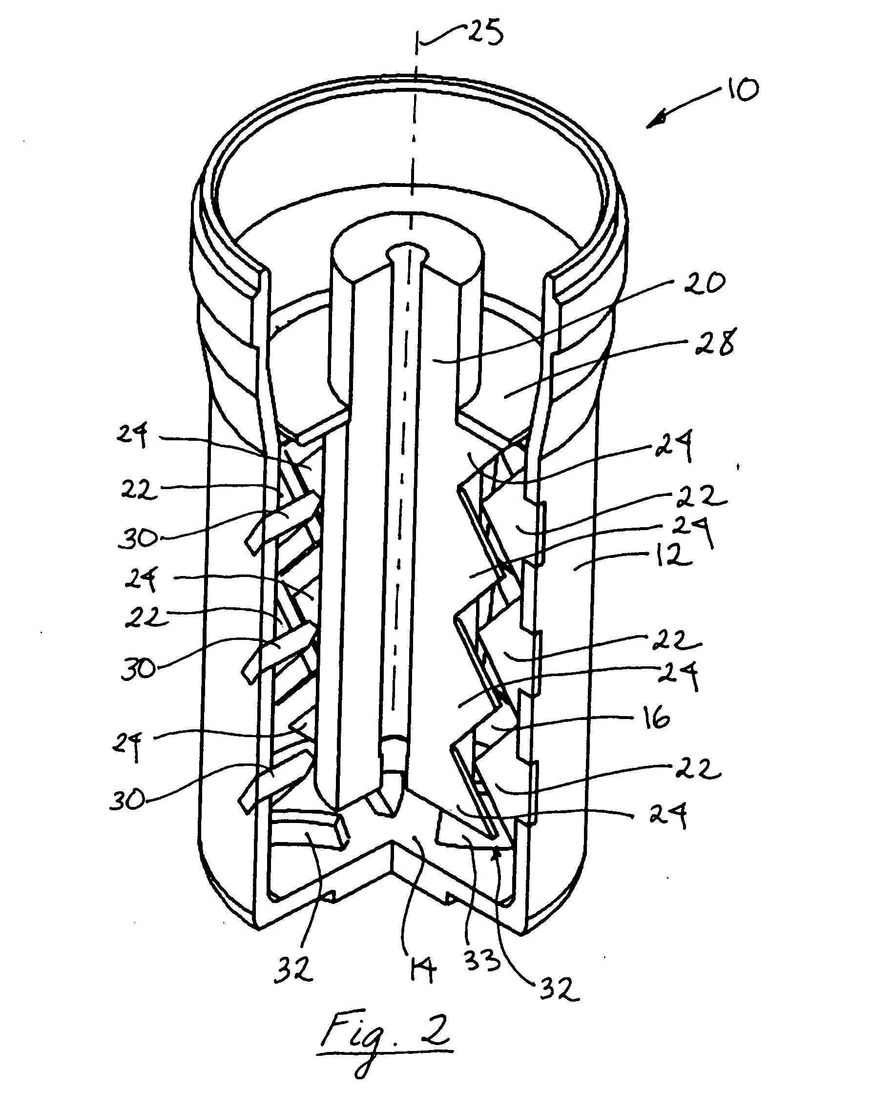
[0030]The present invention meets the foregoing needs by providing novel and improved devices and method for accurately testing viscous and / or elastic fluids, including ones containing particulate before, during, and after cross-linking and before, during, and after breaking. Such devices and methods directly indicate time periods and simulated conditions during which a tested fluid is supporting particulate in suspension and when the tested fluid is not (i.e., when the particulate is settling out of suspension). In addition, the present invention meets the forgoing needs by providing the means with which to continuously monitor the “suspension state” of the fluid system, thus providing for understanding the dynamics that drive particle settling.

[0031]In general, an apparatus according to the invention is or includes a test cell for use in a viscometer having fins or blades, as hereinafter described in more detail, that function to provide vertical lift and homogenization of the lad...


PUM


Abstract

An apparatus for testing a rheological property of a fluid with a particulate includes: (a) a receptacle having a cylindrical side wall enclosed by a bottom wall defining a cavity for receiving a fluid to be tested; (b) an axial support adapted to be positioned in the cavity of the receptacle, whereby relative rotational motion can be imparted to the receptacle and the axial support; (c) at least one inward projection extending inward from an inside surface of the receptacle; (d) at least one outward projection extending outward from the axial support; and (e) at least one projection for directing fluid flow that has at least one major surface angled or curved upward. A method of testing a rheological property of a fluid with a particulate includes: (a) placing a sample of the fluid and the particulate in the apparatus; (b) imparting relative rotational motion to the receptacle and the axial support; and (c) measuring the torque between the receptacle and the axial support. A method of fracturing a subterranean formation penetrated by a well includes: (a) placing a sample of a fracturing fluid and a particulate in the apparatus; (b) imparting relative rotational motion to the receptacle and the axial support; (c) measuring the torque between the receptacle and the axial support; (d) adjusting the conditions for mixing the fracturing fluid and the particulate in response to the measured torque; and (e) injecting the fluid and particulate into the well at a sufficient rate and pressure to fracture the formation.

Description

CROSS-REFERENCE TO RELATED APPLICATIONS[0001]The present application is a continuation of patent application Ser. No. 11 / 246,816, filed on Oct. 7, 2005, entitled “Proppant Suspension Testing Devices And Methods Of Use”, now U.S. Pat. No. ______, issued ______.BACKGROUND[0002]This invention relates generally to improvements in devices and methods that are used to test the rheology of fluids, especially ones containing or mixed with particulate material (subsequently referred to simply as “particulate”). The particular field of use is the oil and gas industry.[0003]Various types of fluids are used in the oil and gas industry. Non-limiting examples include drilling muds, cement, gravel slurries, and stimulation treating fluids. Such fluids are typically pumped into oil or gas wells in known manners. It is desirable to know various characteristics of the fluids to determine how such fluids will act upon being pumped and placed in, or circulated through, the wells.[0004]Rheology is the b...

Claims


Application Information

Patent Timeline
Patent Type & Authority Applications(United States)
IPC IPC(8): E21B43/267
CPCG01N2203/0676G01N11/14
Inventor MORGAN, RICKEY L.JOHNSON, JOHNNY W.MORGAN, RONNIE G.WALTERS, HAROLD G.
Owner HALLIBURTON ENERGY SERVICES INC
Features
  • R&D
  • Intellectual Property
  • Life Sciences
  • Materials
  • Tech Scout
  • Unparalleled Data Quality
  • Higher Quality Content
  • 60% Fewer Hallucinations
Learn More