

Identification Attachments
- Summary
- Abstract
- Description
- Claims
- Application Information
AI Technical Summary
Benefits of technology
Problems solved by technology
Method used
Image

Examples
Embodiment Construction
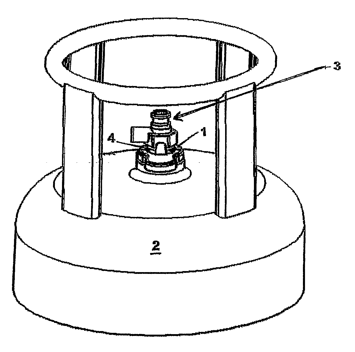
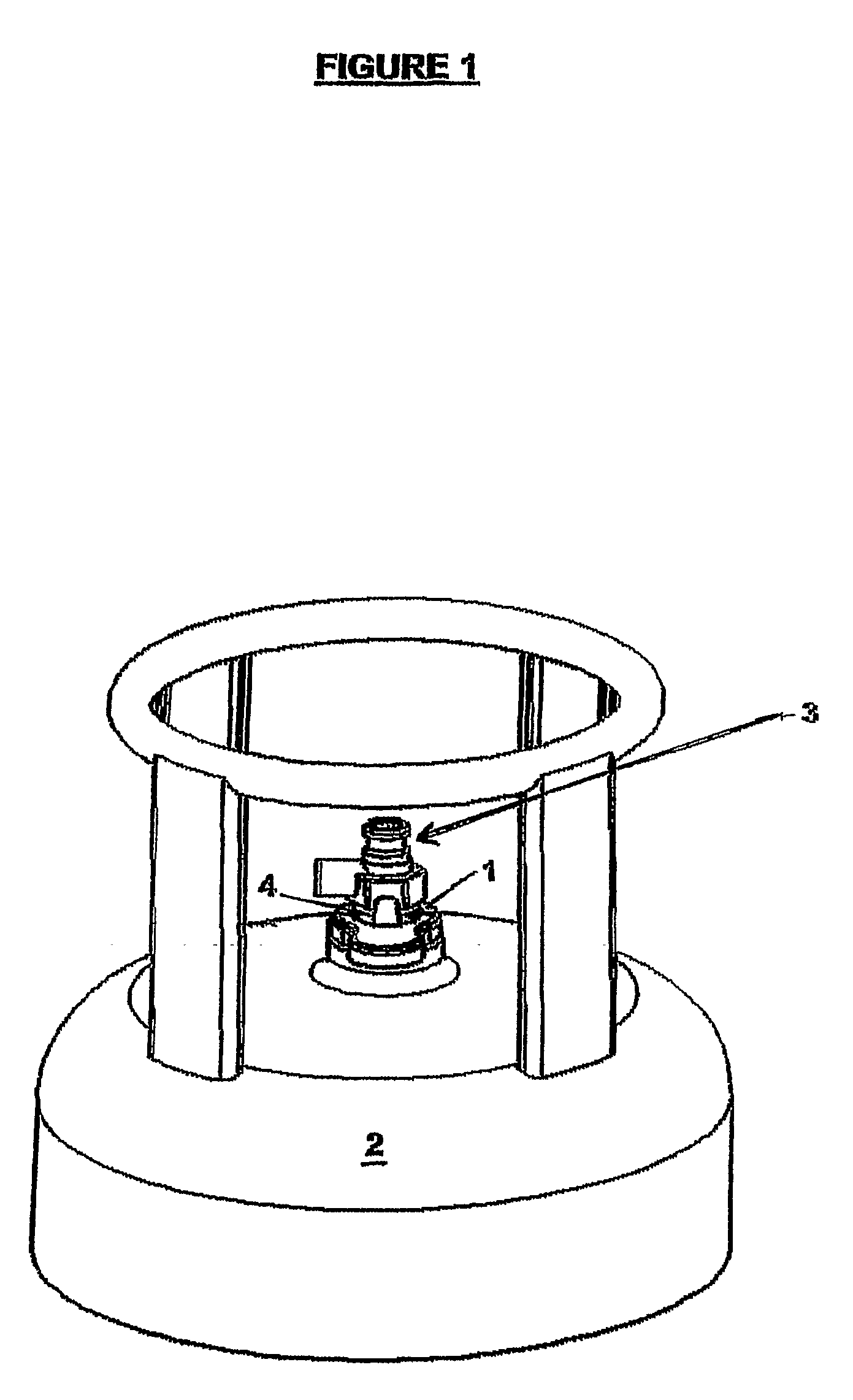
[0090]FIG. 1 shows the identification attachment 1 as it might be used in conjunction with a radio frequency identification tag (not shown) to identify a bottle 2. In use, a Radio Frequency Identification Tag (RFID) would be received within the attachment 1 so that it is located in association with a part of the bottle 2 that is easily accessible. The outlet fitting 3 might be a suitable part. In this embodiment the tag is sealed with the attachment so that it is stored in an environmentally resistant condition.
[0091]To identify the gas bottle 2, a user waves a RFID tag reader (not shown) towards the attachment 1. The attachment 1 houses an RFID tag (not shown) from which is read an identification or inventory number.
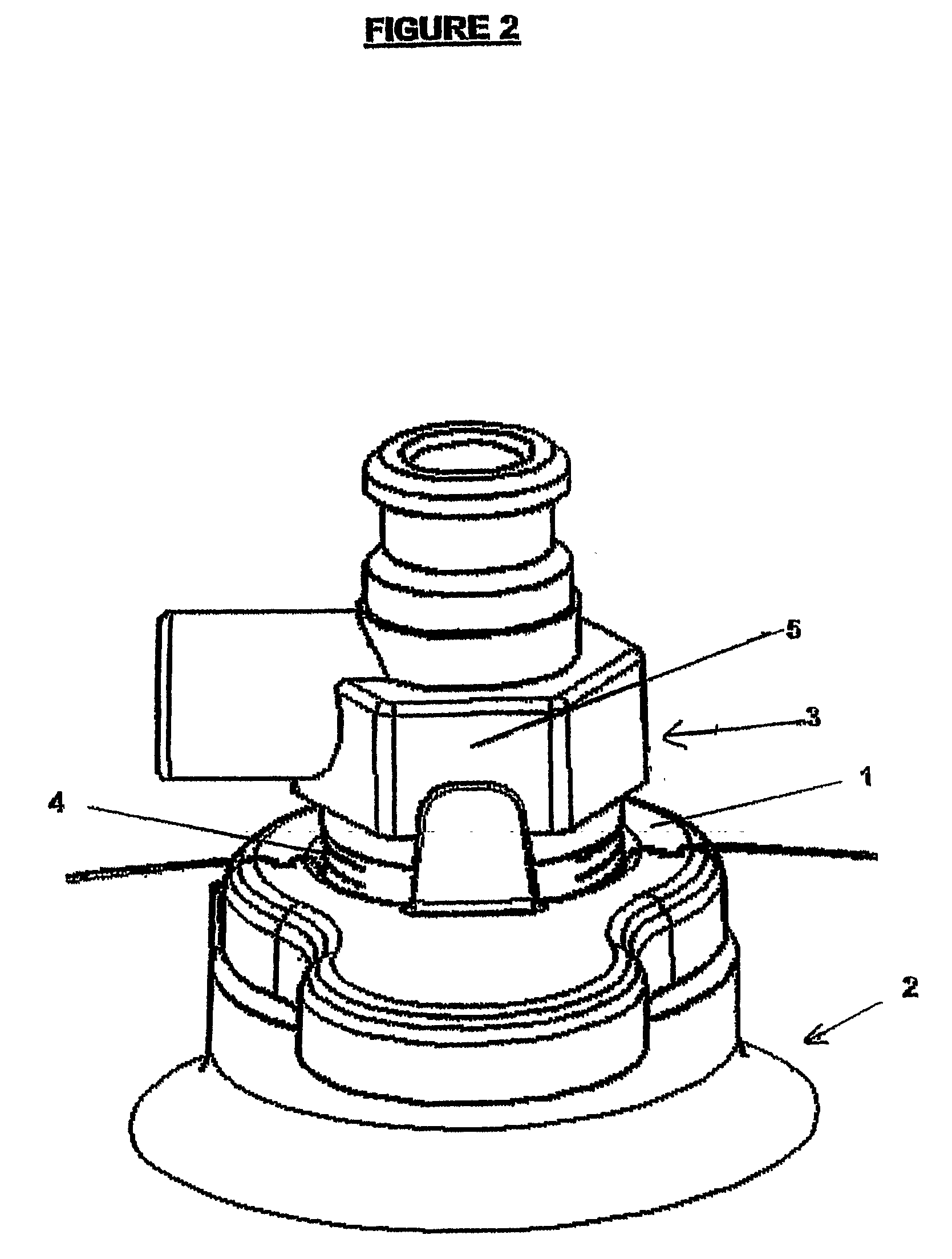
[0092]The gas bottle 2 has an outlet valve 3 which has a neck 4 about which the attachment 1 is secured. This particular gas bottle has a number of flat surfaces 5 above the neck which are provided for use in tightening the valve 3 of the outlet 3 onto the bottle 2.
[009...
PUM
 Abstract
Description
Claims
Application Information