Vertical transformer

Inactive Publication Date: 2008-09-25
DELTA ELECTRONICS INC
View PDF4 Cites 0 Cited by
  • Summary
  • Abstract
  • Description
  • Claims
  • Application Information

AI Technical Summary

Benefits of technology

[0005]The present invention provides a vertical transformer to minimize volume and meet required safety standards of insulation distance of electric devices. An embodiment of the vertical transformer includes a bobbin and a core pair. The bobbin i

Problems solved by technology

However, it is difficult to unify transformer specifications for different types of electronic products.
In addition, potential danger may exist for a transformer for different types of electronic products due to the electric conversion involved.
The large-sized vertical transformer 1 is not suitable for the design of miniature products and costs and materials

Method used


Image

  • Vertical transformer
  • Vertical transformer
  • Vertical transformer

Examples


Example

[0014]The following description is of the best-contemplated mode of carrying out the invention. This description is made for the purpose of illustrating the general principles of the invention and should not be taken in a limiting sense. The scope of the invention is best determined by reference to the appended claims.

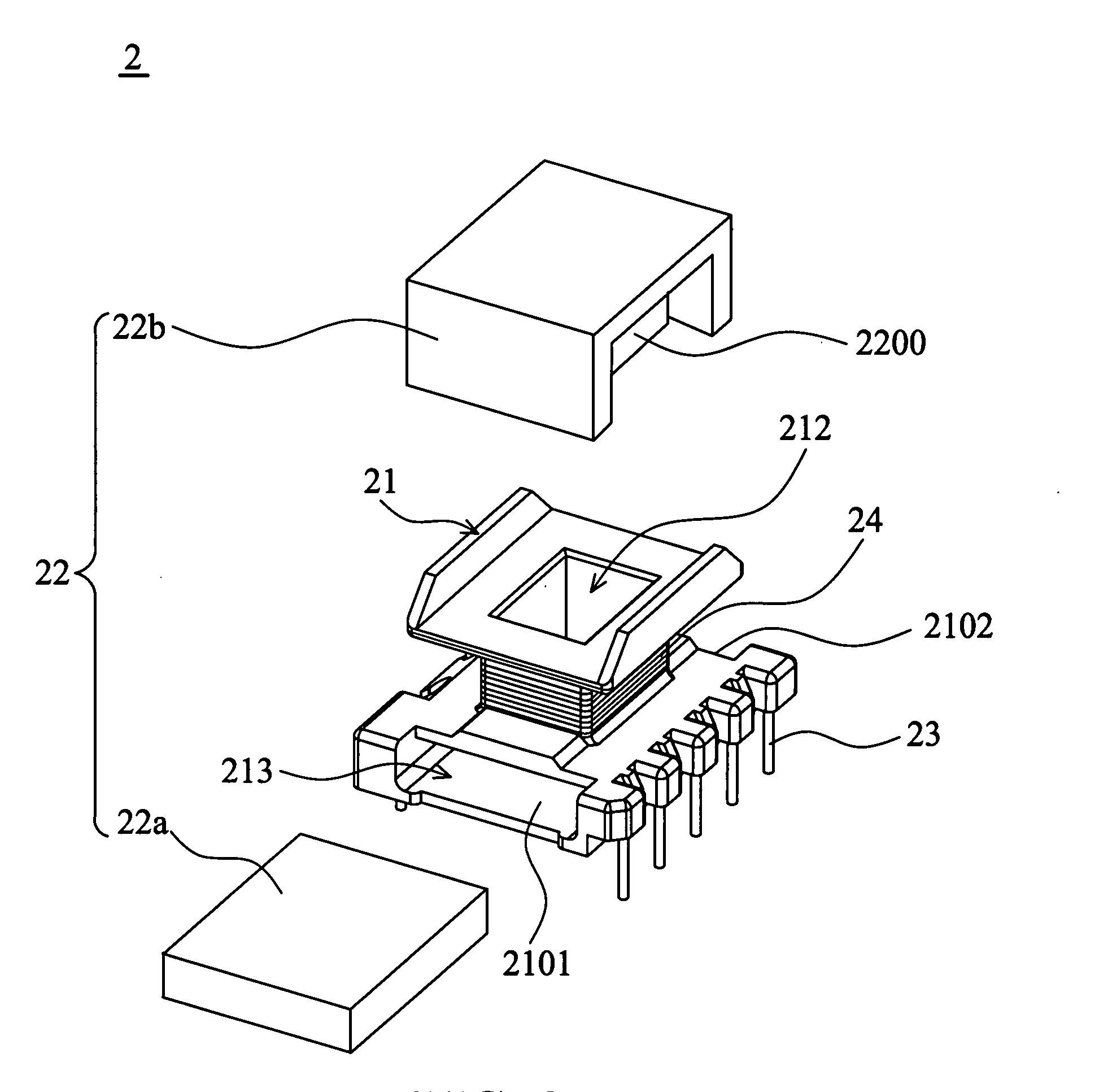
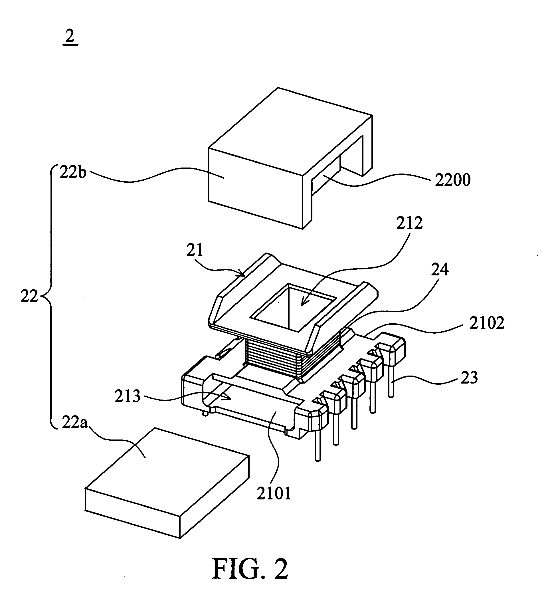
[0015]Referring to FIGS. 2, 3A, 3B and 4 simultaneously, FIG. 2 is an exploded view of a vertical transformer 2 according to the preferred embodiment of the present invention, FIG. 3A is a perspective view of a bobbin 21 of FIG. 2, FIG. 3B is a sectional view of the bobbin 21 along line AA′ in FIG. 3A, and FIG. 4 is a schematic view of the vertical transformer 2 of FIG. 2. The vertical transformer 2 includes the bobbin 21, a core pair 22 including a first core 22a and a second core 22b, and a winding pair 24 including a primary winding and a secondary winding. The bobbin 21 includes a winding region 211, a through hole 212 disposed in the winding region 211, a compartm...


PUM


Abstract

A vertical transformer includes a bobbin and a core pair. The bobbin includes a winding region and a through hole. The through hole is disposed inside the winding region. The core pair includes a first core and a second core. The second core is inserted in the through hole against the first core. The vertical transformer reduces volume and meets required safety standards of the insulation distance of electric devices.

Description

BACKGROUND OF THE INVENTION[0001]This Non-provisional application claims priority under U.S.C. §119(a) on Patent Application No(s). 0962045438, filed in Taiwan, Republic of China on Mar. 21, 2007, the entire contents of which are hereby incorporated by reference.FIELD OF THE INVENTION [0002]The invention relates to a vertical transformer, and more particularly to a vertical transformer capable of reducing the volume and meeting the safety standards.DESCRIPTION OF THE RELATED ART [0003]With the rapid development of technology, the application of electronic products is extensive. The process of converting drive voltage of electrical circuits in a transformer determines the stability of the supply of power. However, it is difficult to unify transformer specifications for different types of electronic products. In addition, potential danger may exist for a transformer for different types of electronic products due to the electric conversion involved. Thus, the transformer must be met sa...

Claims


Application Information

Patent Timeline
IPC IPC(8): H01F27/30
CPCH01F27/306H01F27/06
Inventor KUNG, CHING-SUNGHE, HANDYLI, JOHNSON
Owner DELTA ELECTRONICS INC
Why Eureka
Try Eureka