Concentric Clamping for Drill Spindles

Active Publication Date: 2008-09-25
THE BOEING CO
View PDF7 Cites 5 Cited by
  • Summary
  • Abstract
  • Description
  • Claims
  • Application Information

AI Technical Summary

Benefits of technology

[0007]Concentric clamping assemblies for drilling equipment in accordance with the present disclosure may advantageously provide improved clamping using assemblies that are lighter and less bulky than comparable prior art systems.

Problems solved by technology

These external actuators add significant bulk to the spindle and reduce workpiece accessibility.
The actuators and support structures also add weight to the drill spindle.

Method used


Image

  • Concentric Clamping for Drill Spindles
  • Concentric Clamping for Drill Spindles
  • Concentric Clamping for Drill Spindles

Examples


Embodiment Construction

[0022]The present disclosure teaches clamping assemblies for drilling equipment, and more specifically, methods and systems for concentric clamping for drill spindles. Many specific details of certain embodiments of the invention are set forth in the following description and in FIGS. 1-10 to provide a thorough understanding of such embodiments. One skilled in the art, however, will understand that the invention may have additional embodiments, or that the invention may be practiced without several of the details described in the following description.

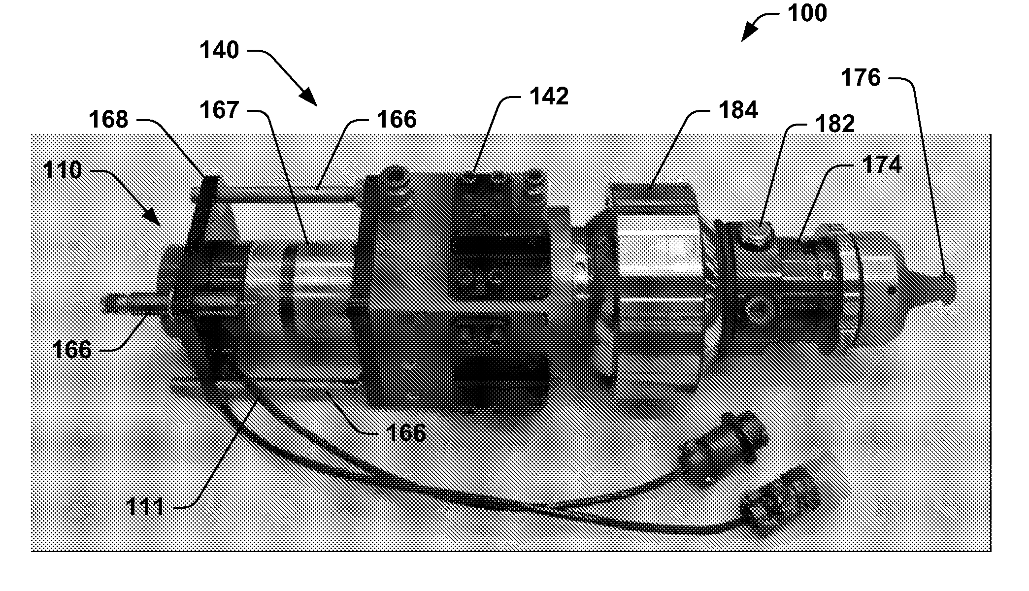
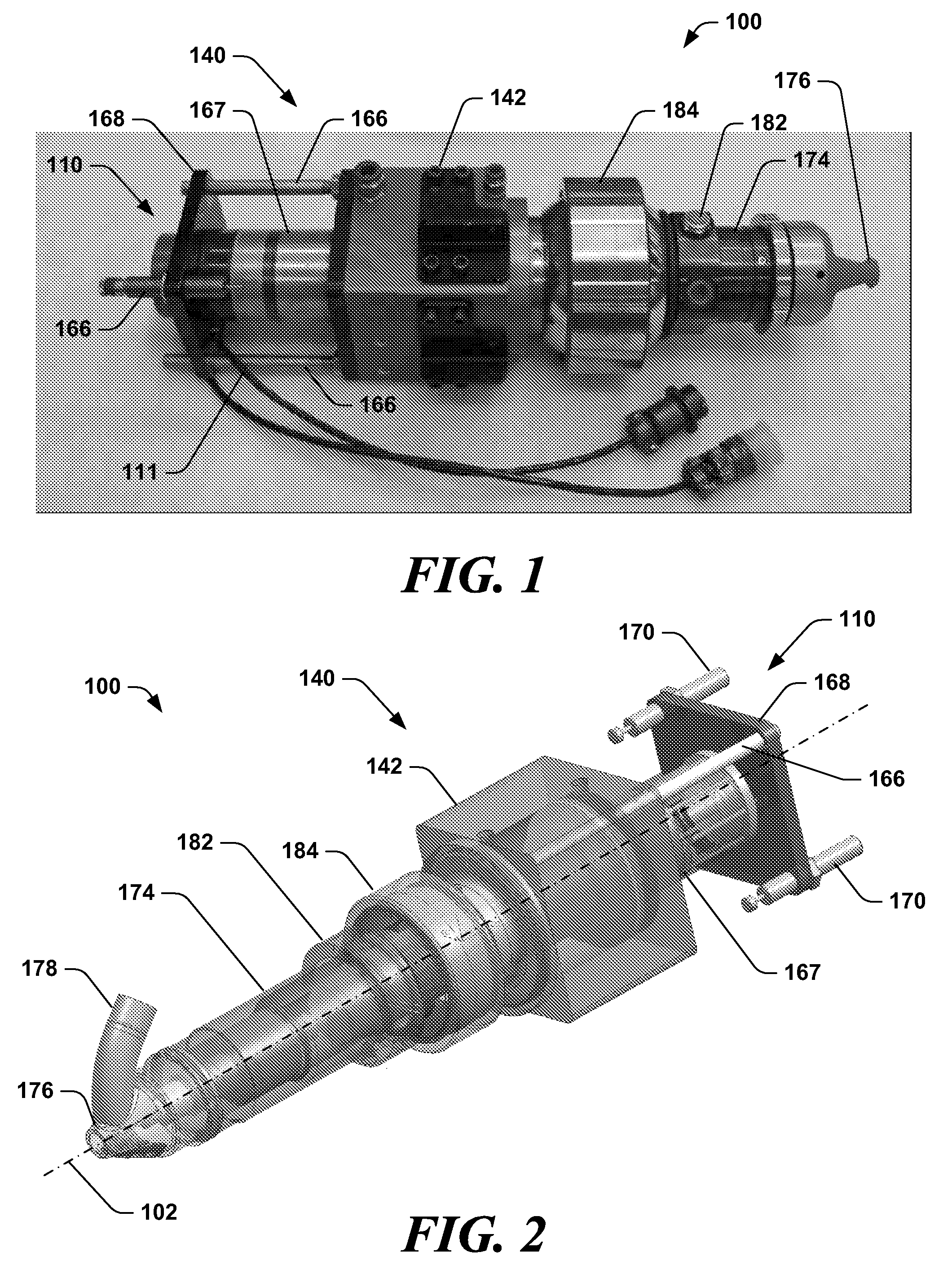
[0023]FIGS. 1 and 2 are elevational and isometric views of a drill assembly 100 in accordance with an embodiment of the invention. In this embodiment, the drill assembly 100 includes a spindle assembly 110 that performs the actual drilling operations on a workpiece, and a clamping assembly 140 that clamps and secures the workpiece during the drilling operations performed by the spindle assembly 110. The spindle assembly 110 may be of a...


PUM

PropertyMeasurementUnit
Forceaaaaaaaaaa
Pressureaaaaaaaaaa

Abstract

Methods and systems for concentric clamping for manufacturing assemblies are disclosed. In one embodiment, a drilling assembly includes a spindle assembly configured to perform a drilling operation at a drilling location on a workpiece, and a clamping assembly having an actuator concentrically disposed about the spindle assembly. A nosepiece is coupled to the actuator and is configured to apply a clamping force concentrically about the drilling location on the workpiece. The actuator may include an inner housing having an outwardly extending flange, and an outer housing disposed about the flange of the inner housing. Pressurization of a first chamber moves the inner housing forwardly and applies the clamping force of the nosepiece against the workpiece, and pressurization of a second chamber moves the inner housing aftwardly and retracts the nosepiece away from the workpiece.

Description

CROSS REFERENCE TO RELATED APPLICATIONS[0001]This patent application is related to co-pending, commonly-owned U.S. patent application Ser. No. (t.b.d.) entitled “Drill Spindles with Inline Direct Drive Feed” filed on Mar. 23 2007 under Attorney Docket No. BO1-0421US, which application is incorporated herein by reference.FIELD OF THE INVENTION[0002]The field of the present disclosure relates to clamping assemblies for drilling equipment, and more specifically, to methods and systems for concentric clamping for drill spindles.BACKGROUND OF THE INVENTION[0003]When drilling single or multi-layer stacks, a favored method of stabilizing the drill spindle and workpiece is to press an independently actuated device extending forward of a drill spindle, known as a nosepiece or pressure foot, onto the workpiece surface. Applying this clamping force to multi-layers stacks reduces or eliminates interlaminar burrs from the drilling operation, and prevents drill chips from getting between the laye...

Claims


Application Information

Patent Timeline
IPC IPC(8): B23B47/00
CPCB23Q3/002Y10T408/6757Y10T408/03Y10T408/56245Y10T408/563
Inventor MATHIS, DENNIS R.
Owner THE BOEING CO
Why Eureka
Try Eureka