
Rapid attach and release clamps

Active Publication Date: 2012-05-01
BAXTER HEALTHCARE SA +1
View PDF67 Cites 38 Cited by
  • Summary
  • Abstract
  • Description
  • Claims
  • Application Information

AI Technical Summary

Benefits of technology

[0016]It is accordingly an advantage of the present disclosure to provide an improved clamp for attaching medical devices to a structure.
[0017]It is another advantage of the present disclosure to provide a rapid attach clamp for quickly attaching a medical device to a pole.
[0018]It is yet another advantage of the present disclosure to provide a rapid release clamp for quickly releasing a medical device from a pole.

Problems solved by technology

However, there are several disadvantages inherent in the currently available clamping assemblies.
Some clamping assemblies are limited as to the size or shape, or both, of the IV pole to which they can attach.
While a clamp on a clamping assembly may be capable of attaching to a round IV pole, it may not be capable of attaching to a hexagonal or square shaped pole.
Some clamps are limited to specific widths or diameters of poles to which they can properly attach.
Each of these limitations restricts the adaptability and limits the usefulness of the clamping assembly.
An additional drawback is the effort required for positioning the clamp on a pole or repositioning the clamp on the same pole or on a different pole.
Some clamps require an extended amount of time and effort to manually attach the medical device to the pole.

Method used


Image

  • Rapid attach and release clamps
  • Rapid attach and release clamps
  • Rapid attach and release clamps

Examples


Embodiment Construction

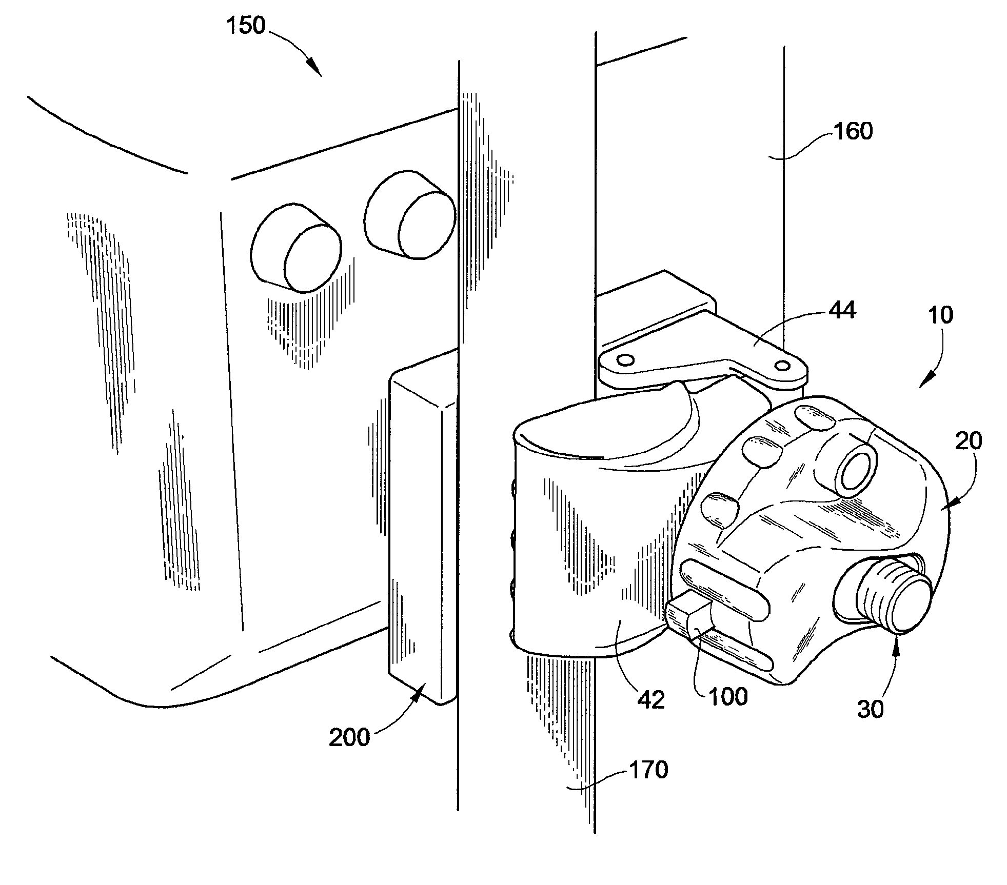
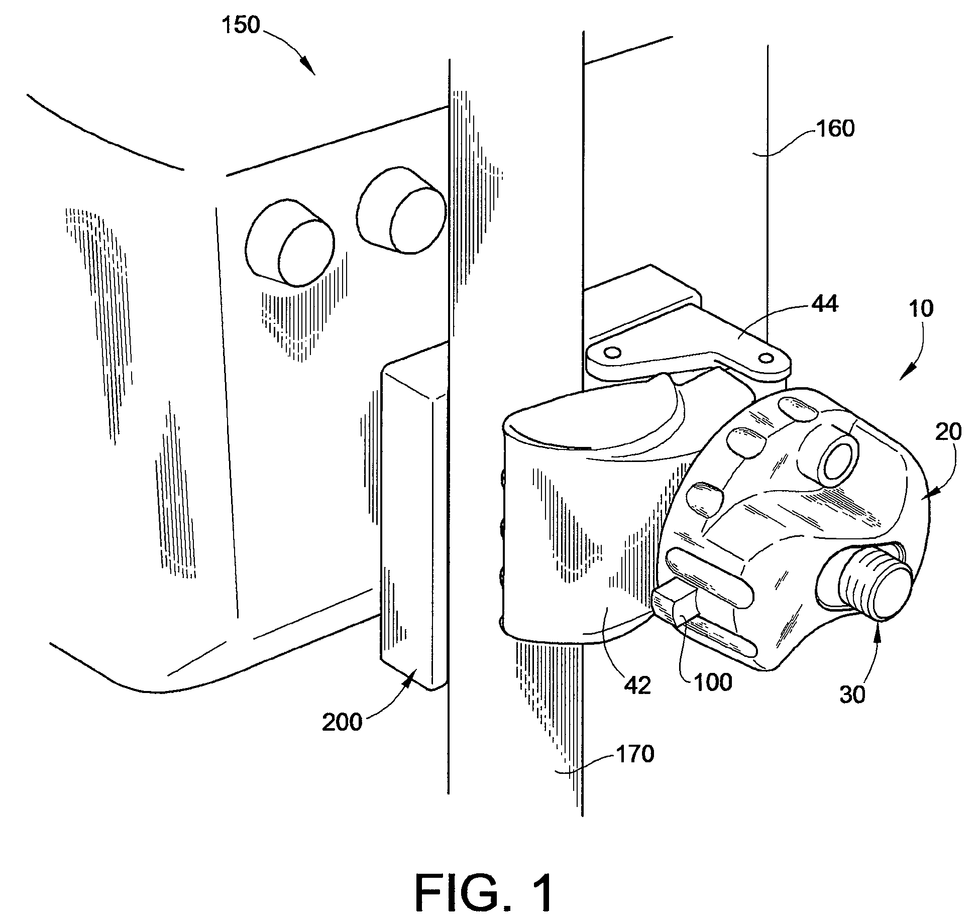
[0027]Referring now to the drawings and in particular to FIG. 1, one embodiment of the rapid attach and release clamp 10 of the present disclosure operating with a medical device system 150 is illustrated. Clamp 10 and the various components of clamp 10 can be made using any suitable materials such as metals, polymers and plastics. Thus, clamp 10 can be designed to have a light weight, high strength, and durability. System 150 includes clamp 10, support base 200, a medical device 160, such as a infusion pump, and an intravenous (“IV”) support pole 170. Any suitable medical device 160 can be used in system 150.

[0028]Clamp 10 enables medical device 160 to be easily clamped and unclamped to support pole 170, allowing device 160 to be moved up and down as necessary. Clamp 10 also allows medical device 160 to be rotated about pole 170 and clamped at a desired radial position relative to support pole 170.

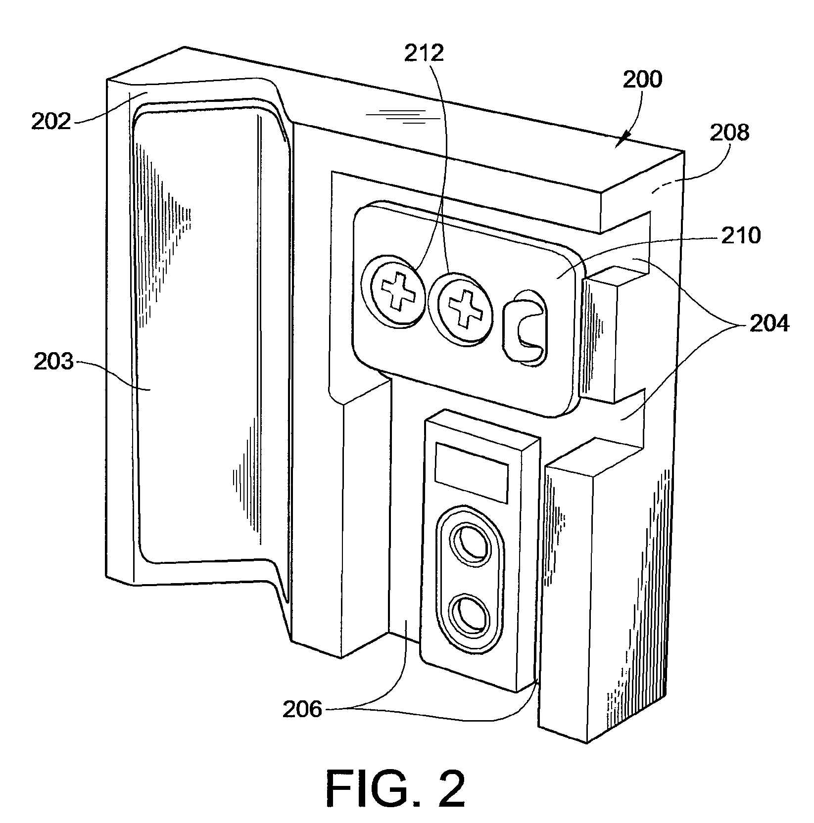
[0029]As illustrated in FIG. 2, in an embodiment, support base 200 contains a section...


PUM


Abstract

Rapid attach and release clamps for attaching to supports include a threaded rod, an arm pivotally attached to the threaded rod, and a knob having an exterior surface and an interior surface. The knob defines a passageway sized to fit the threaded rod. A lock comprises at least one thread and is rotatably attached to the interior surface of the knob. The lock is constructed and arranged to move between a closed position with the thread entering the passageway and engaging the threaded rod and an open position with the thread not entering the passageway. A lever is moveably attached to the clamp and constructed and arranged to rotate the lock about a pivot point.

Description

BACKGROUND[0001]The present disclosure is in the general field of clamps for securing objects to supporting poles, and in particular, for supporting medical devices connected to a patient on a supporting structure or pole.[0002]One of the more basic tools used in a medical environment is an intravenous (“IV”) stand. The typical IV stand includes an elongated member, or pole, that may be oriented either vertically or horizontally, and may additionally have any one of a variety of cross-sectional geometric shapes, including round, hexagonal or square. The pole is placed upon and supported by a pedestal. Typically, IV devices such as supply bags or bottles of an IV liquid—normally blood, saline solution, or medication—are attached to the IV pole. These liquids are then delivered via a thin tube to a patient who is in a bed adjacent the IV stand.[0003]As medical technologies and treatment techniques have advanced, the number of different IV liquids that are delivered to a patient has in...

Claims


Application Information

Patent Timeline
IPC IPC(8): A47B96/06
CPCA61M39/283
Inventor SPANG, JR., RONALD H.MARCHESE, JOHN
Owner BAXTER HEALTHCARE SA
Learn More