Molds capable of overcoming molding defects of simplicity in shrinkage, difficulty in cement saturation and air exhaust and the like

A mold core and glue position technology, which is applied in the field of plastic molds, can solve the problems of slow heat dissipation in the core, cold glue that cannot be solved by exhaust grooves, and reduced mold life, so as to improve the trapped air, the problem of insufficient glue, and the shrinkage problem effect

Inactive Publication Date: 2011-11-30
阳恒
View PDF6 Cites 15 Cited by
  • Summary
  • Abstract
  • Description
  • Claims
  • Application Information

AI Technical Summary

Problems solved by technology

[0002] The following molding defects often exist in the injection molding of traditional ordinary injection molding machines: 1. Shrinkage - refers to uneven cooling and shrinkage of the product due to too thick local glue after injection: the heat dissipation in the center of the thick glue is slow on the surface And other thin rubber parts will continue to shrink after cooling and solidification, resulting in the formation of a pit on the surface of the product and affecting the appearance of the product
2. Due to the relatively thin glue thickness at a certain part of the product (referred to as the thin glue position), it is difficult to run the glue during molding (it is easy to lack glue during molding), trapped air and weld lines, etc.
3. Trapped air----refers to the hot-melt glue flow from the glue inlet to all parts of the product during injection molding, but when the glue flow reaches the last position or a local thin glue position, the mold cavity The gas cannot be discharged and there is a backlog or the material flow process is relatively far away when reaching this position, there is already cold glue, which affects the appearance of the product surface
However, usually increasing the injection pressure still cannot completely solve the problem, or the two problems are solved, but due to the increase of the injection pressure, the parting surface of the product is caused (burrs), the mold is deformed, and the life of the mold is significantly reduced. New problems such as increased machine power consumption have emerged
2. In order to solve the trapped air or cold glue, add an exhaust groove or overflow hole in the trapped air. The exhaust groove cannot solve the cold glue and some positions cannot be added with an exhaust groove, but can only be solved by adding an overflow hole.
However, because the overflow hole is connected with the product, it will be separated after shaving, which increases the cost of post-processing and affects the quality of the product.
[0003] After retrieving the published literature, it is not found that there is a technology that uses the same technology as the oil cylinder and structural principle of this technology on the plastic mold

Method used


Image

  • Molds capable of overcoming molding defects of simplicity in shrinkage, difficulty in cement saturation and air exhaust and the like
  • Molds capable of overcoming molding defects of simplicity in shrinkage, difficulty in cement saturation and air exhaust and the like
  • Molds capable of overcoming molding defects of simplicity in shrinkage, difficulty in cement saturation and air exhaust and the like

Examples


Embodiment 1

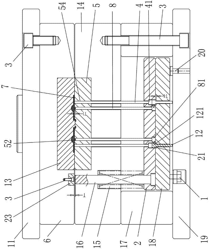
[0048] This mold (such as figure 1 As shown, the state before glue replenishment) is composed of static mold base 11, static template 6, movable mold base 19, movable mold plate 14, mold foot 17, injection molding machine top roller 22 and thick glue filling mechanism.

[0049] Static mold base 11 is provided with static template 6 below static template 6, is provided with static mold core 13 in static mold core 13, is provided with product mold cavity 53 in static mold core 13.

[0050] Die feet 17 are arranged on the movable mold base 19, a movable template 14 is arranged on the mold feet 17, a movable mold core 5 is arranged in the movable template 14, and product thimbles are arranged successively between the mold feet 17 from bottom to top. The top plate 18 and the product thimble fixing plate 2 are provided with a chute 21 on the product thimble fixing plate 2, and the product thimble 4 passes through the product thimble fixing plate 2 and the movable mold core 5 and con...

Embodiment 2

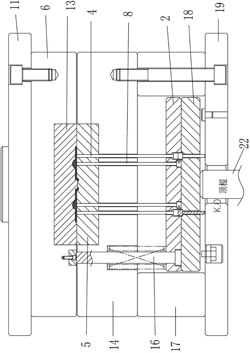
[0057] This mold (such as image 3 As shown, the state before glue replenishment) is composed of a static mold base 11, a static template 6, a movable mold base 19, a movable template 14, a mold foot 17, an injection molding machine top roller 22, and a thin rubber-position forming mechanism.

[0058] Static mold base 11 is provided with static template 6 below static template 6, is provided with static mold core 13 in static mold core 13, is provided with product mold cavity 53 in static mold core 13.

[0059] Die feet 17 are arranged on the movable mold base 19, a movable template 14 is arranged on the mold feet 17, a movable mold core 5 is arranged in the movable template 14, and product thimbles are arranged successively between the mold feet 17 from bottom to top. The top plate 18 and the product thimble fixing plate 2 are provided with a chute 21 on the product thimble fixing plate 2, and the product thimble 4 passes through the product thimble fixing plate 2 and the mov...

Embodiment 3

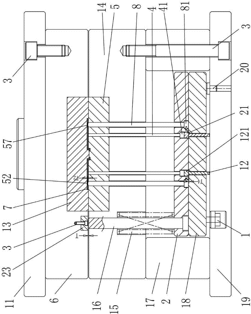
[0066] This mold (such as Figure 5 As shown, the state before glue replenishment) is composed of static mold base 11, static template 6, movable mold base 19, movable template 14, mold foot 17, injection molding machine top roller 22 and automatic in-mold cutting overflow hole mechanism.

[0067] Static mold base 11 is provided with static template 6 below static template 6, is provided with static mold core 13 in static mold core 13, is provided with product mold cavity 53 in static mold core 13.

[0068] Die feet 17 are arranged on the movable mold base 19, a movable template 14 is arranged on the mold feet 17, a movable mold core 5 is arranged in the movable template 14, and product thimbles are arranged successively between the mold feet 17 from bottom to top. The top plate 18 and the product thimble fixing plate 2 are provided with a chute 21 on the product thimble fixing plate 2, and the product thimble 4 passes through the product thimble fixing plate 2 and the movable...


PUM


Abstract

The invention discloses molds capable of overcoming molding defects of simplicity in shrinkage, difficulty in cement saturation and air exhaust and the like. In the molds, a first mold is used for supplementing cement at a local thick cement position in an injection molding machine mold with a mold-closing ejection signal or a front mold core-pulling signal, and a cement supplementing mechanism which is used for supplementing the cement to the thick cement position of a product is arranged in a movable mold core; a second mold is used for forming a local thin cement position in the injection molding machine mold with the mold-closing ejection signal or the front mold core-pulling signal, and a forming mechanism which is used for forming the thin cement position of the product is arranged in the movable mold core; and a third mold is used for a mechanism for automatically cutting the overflowed cement of a material overflowing hole in the injection molding machine mold with the mold-closing ejection signal or the front mold core-pulling signal, and the mechanism which is used for automatically cutting the overflowed cement of the material overflowing hole in the mold is also arranged in the movable mold core.

Description

technical field [0001] The present invention relates to the plastic mold of ordinary injection molding machine, mainly refers to the injection molding machine with closed mold ejection signal or with front mold core pulling signal to solve the problem of easy shrinkage of plastic parts in thick parts of plastic products; difficulty in filling glue in parts of thin parts; clamping water line Coarse; Difficult to exhaust; Molds with molding defects such as cold glue. Background technique [0002] The following molding defects often exist in the injection molding of traditional ordinary injection molding machines: 1. Shrinkage - refers to uneven cooling and shrinkage of the product due to too thick local glue after injection: the heat dissipation in the center of the thick glue is slow on the surface And other thin rubber parts will continue to shrink after cooling and solidification, resulting in the formation of a pit on the surface of the product and affecting the appearance...

Claims


Application Information

Patent Timeline
Patent Type & Authority Applications(China)
IPC IPC(8): B29C45/26B29C45/40B29C45/34B29C45/38
Inventor 阳恒
Owner 阳恒
Why Eureka
Try Eureka