
Signaling method to support geo-location emergency services

a geo-location emergency and signaling technology, applied in the field of wireless communication, can solve the problems of increasing capacity, affecting the quality of emergency service communications in the wireless network, and not allowing for the collation of information at the source base station, so as to reduce the bandwidth usage of the network

Active Publication Date: 2008-09-25
ALCATEL LUCENT SAS
View PDF5 Cites 33 Cited by
  • Summary
  • Abstract
  • Description
  • Claims
  • Application Information

AI Technical Summary

Benefits of technology

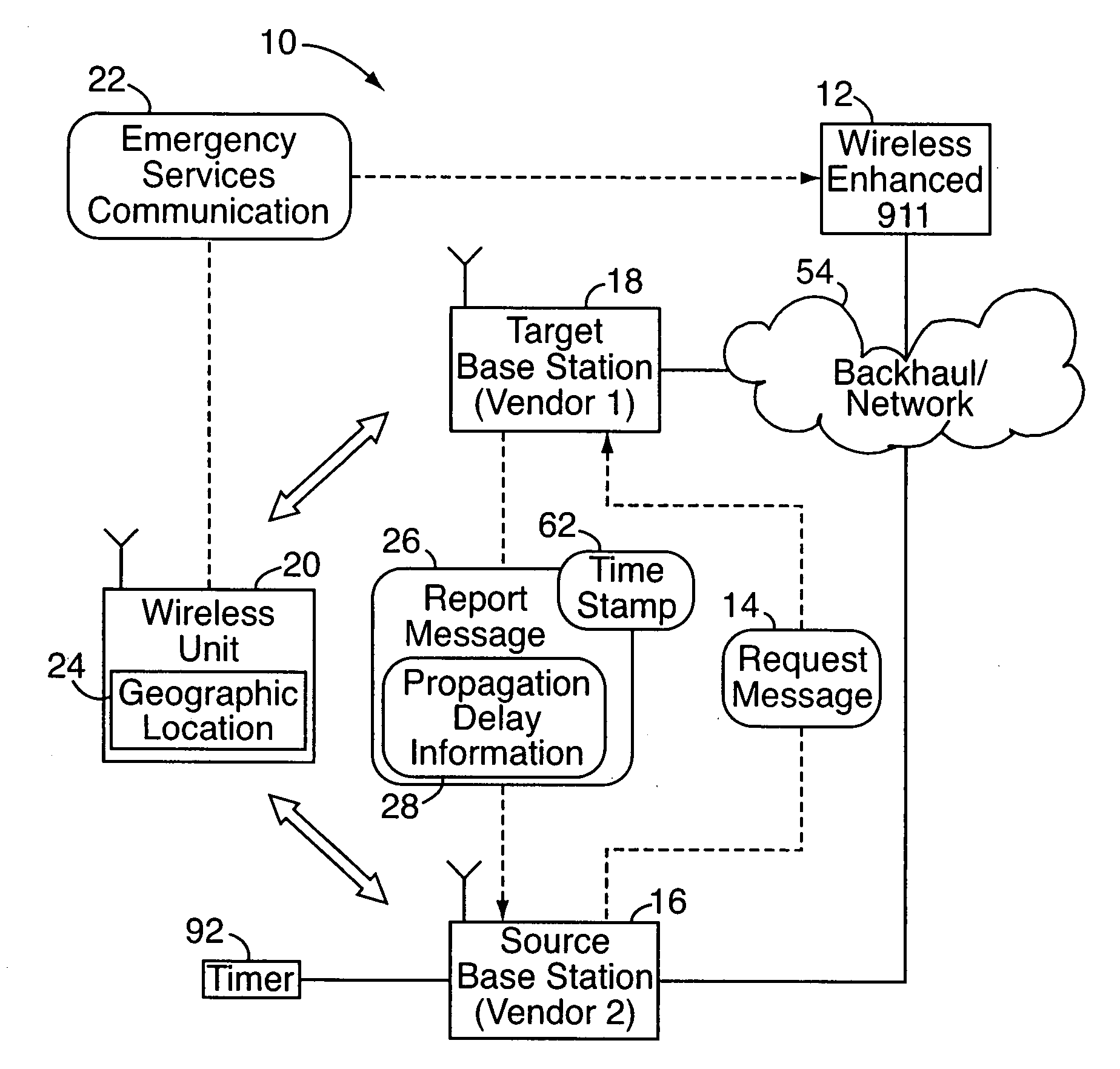
[0008]In another embodiment, communication protocols in the wireless network are configured so that base stations transmit propagation delay information only upon the receipt of request messages requesting the propagation delay information. Thus, there are no automatic transmissions in the network of propagation delay information, either upon a base station acquiring a wireless unit or when the wireless unit's propagation delay changes. Since propagation delay information is transmitted only when required, this results in a reduction of bandwidth usage in the network.
[0009]The aforementioned method is particularly beneficial in situations where the target base station and the source base station are operated by different vendors, that is, by different, unrelated companies. In particular, unlike in conventional networks, the communications method of the present invention provides a mechanism for the source base station of one vendor to request a wireless unit's propagation delay information from a target base station of another vendor at any time when a geo-location emergency service is needed, e.g., when an emergency services-related communication is initiated that requires or warrants a network-based determination of wireless unit location.

Problems solved by technology

Soft handoff requires less power, which reduces interference and increases capacity.
Current communication standards, however, do not allow for the collation of this information at a source base station at the particular time when an emergency service request is initiated at a wireless unit.
This may result poor quality or malfunctioning emergency service communications in the wireless network.

Method used


Image

  • Signaling method to support geo-location emergency services
  • Signaling method to support geo-location emergency services
  • Signaling method to support geo-location emergency services

Examples


Embodiment Construction

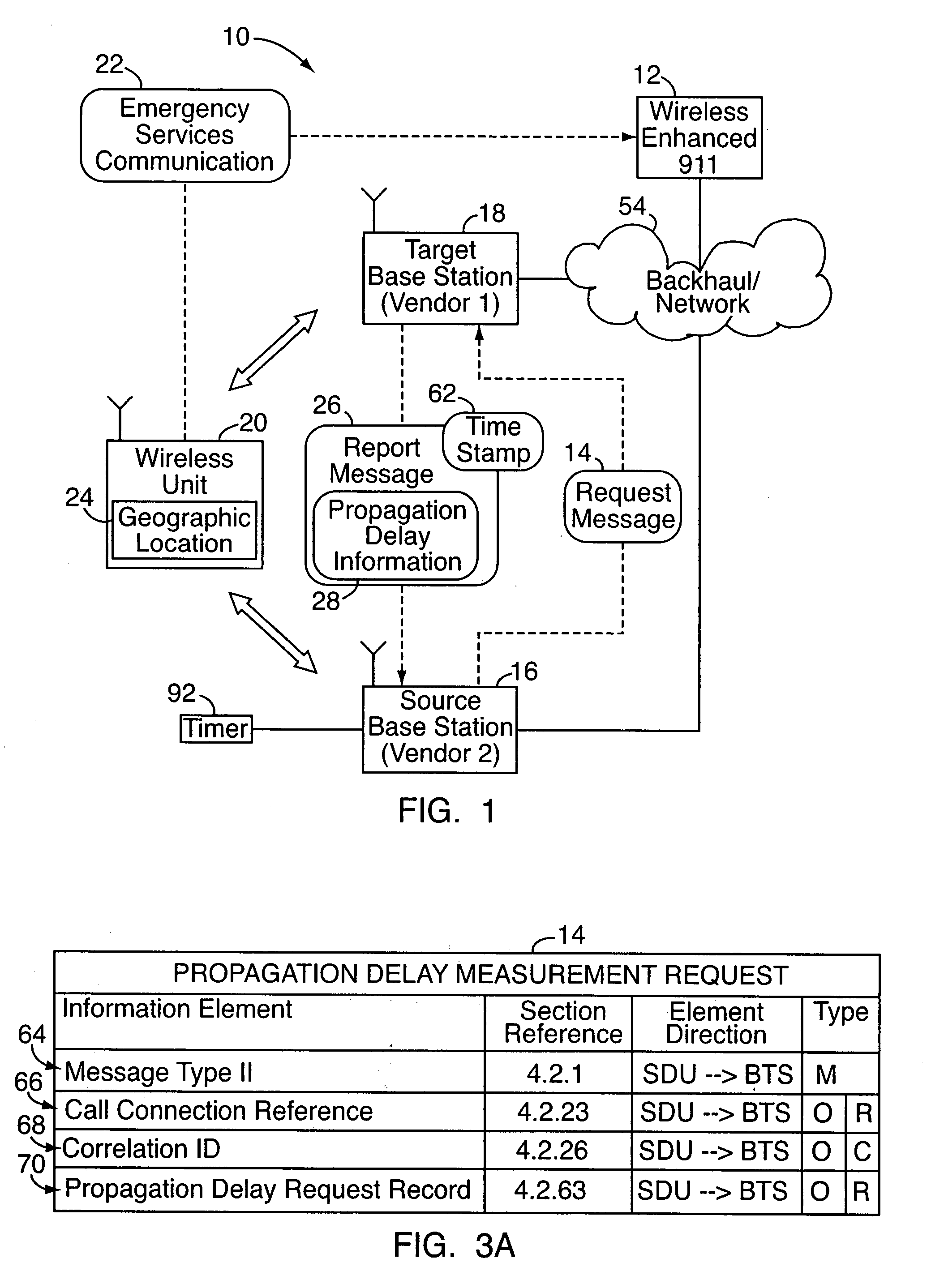
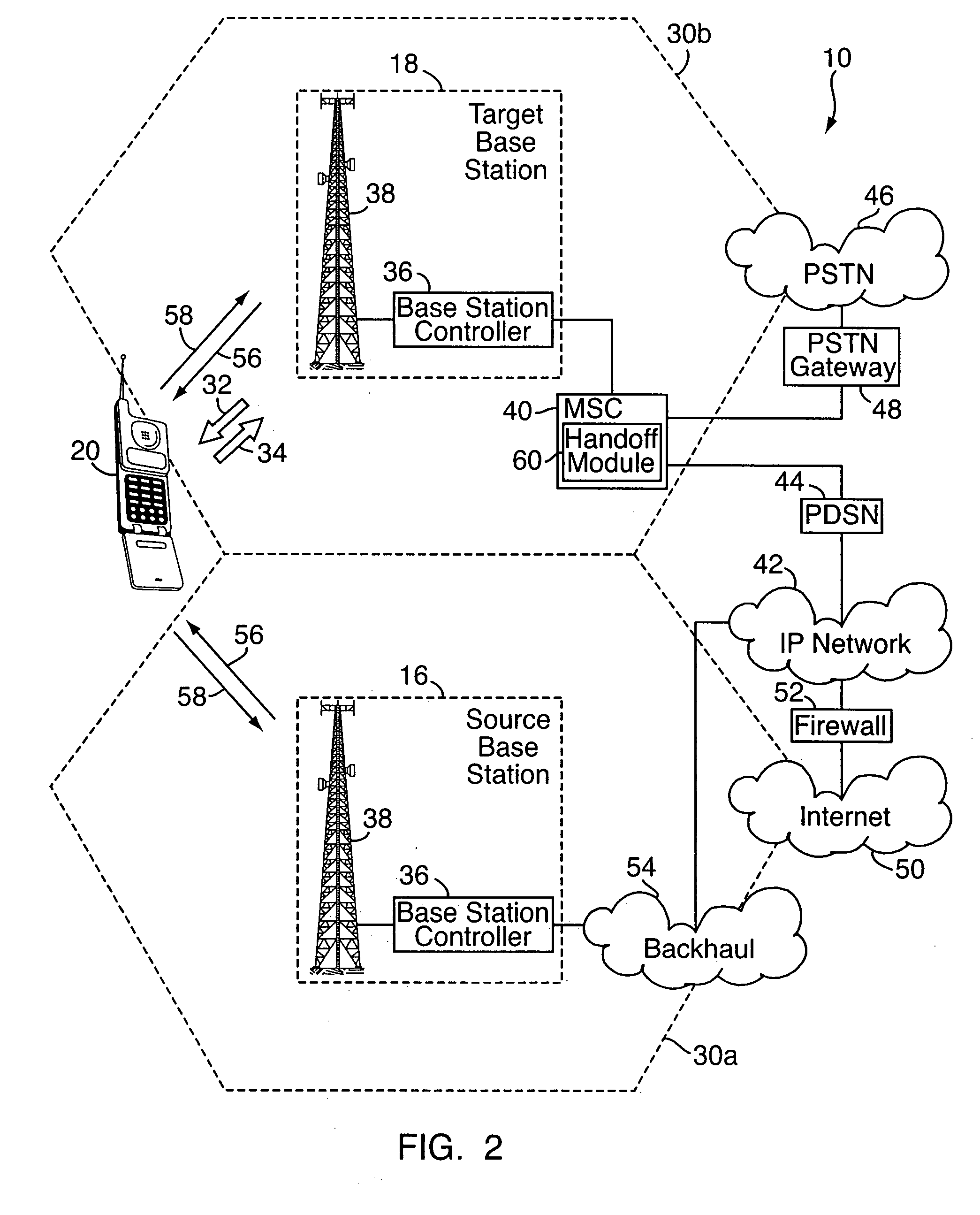
[0015]With reference to FIGS. 1-4C, an embodiment of the present invention relates to a method and system for communicating in a wireless network 10, e.g., a signaling method to support geo-location emergency services 12 in the network. According to the method, a request message 14 is transmitted from a source base station 16 to a target base station 18. For example, the request message 14 might be sent subsequent to a wireless unit 20 initiating an emergency services communication 22, if it is desired to determine the location 24 of the wireless unit. Upon receiving the request message 14, the target base station 18 transmits a report message 26 to the source base station 16. The report message 26 includes propagation delay information 28 associated with the wireless unit, e.g., a one-way transmission delay of the wireless unit as measured at the target base station. The propagation delay information 28 may be used as part of a process for determining the location of the wireless u...


PUM


Abstract

In a method to support geo-location emergency services in a wireless network, a request message is transmitted from a source base station of one vendor to a target base station of another vendor. For example, the request message might be sent subsequent to a wireless unit initiating an emergency services communication, where it is desired to determine the location of the wireless unit by radiolocation, or otherwise at the network level. Upon receiving the request message, the target base station transmits a report message to the source base station, which includes a one-way transmission delay (or other propagation delay information) of the wireless unit as measured at the target base station. Communication protocols in the network are configured so that there are no automatic transmissions of propagation delay information. Instead, base stations transmit propagation delay information only upon the receipt of request messages requesting the information.

Description

[0001]This application claims the benefit of U.S. Provisional Application Ser. No. 60 / 919,244, filed Mar. 21, 2007, which is hereby incorporated by reference herein in its entirety.FIELD OF THE INVENTION[0002]The present invention relates to wireless communications and, more particularly, to soft handoff in the context of geo-location services.BACKGROUND OF THE INVENTION[0003]In a typical radio frequency (“RF”) communication network, data and other signals are transmitted from one or more fixed base stations to one or more wireless units. Because most wireless units are carried between different locations, e.g., home, car, and work, the distance between a wireless unit and each of a network's base stations will typically vary over time. As the wireless unit moves away from one base station and towards another, because the wireless unit has a limited range, it may be necessary to transfer support of the wireless units between the two base stations. This process is referred to as “han...

Claims


Application Information

Patent Timeline
IPC IPC(8): H04M11/04H04W4/90H04W36/08H04W64/00
CPCH04W36/08H04W64/00H04W4/90H04W76/50
Inventor WANG, LIWAZHU, PENGFEI
Owner ALCATEL LUCENT SAS
Learn More