Method and apparatus for transferring files to clients using a peer-to-peer file transfer model and a client-server transfer model

a file transfer model and client-server technology, applied in the field of methods and apparatus for transferring files to clients using a peer-to-peer file transfer model and a client-server transfer model, can solve the problems of linear increase in bandwidth requirements and rapid increase in cos

Inactive Publication Date: 2008-09-25
SONY CORP +1
View PDF33 Cites 183 Cited by
  • Summary
  • Abstract
  • Description
  • Claims
  • Application Information

AI Technical Summary

Benefits of technology

[0004]In accordance with the present invention, a method and apparatus is provided for delivering a content file to a client over a packet-switched network. The method begins by determining a suitable throughput required to deliver the content file to the client. Next, the throughput available in a peer-to-peer network for delivering the content file to the client is dete

Problems solved by technology

With conventional Hypertext Transfer Protocol (HTTP) file delivery techniques, for example, the bandwidth req

Method used


Image

  • Method and apparatus for transferring files to clients using a peer-to-peer file transfer model and a client-server transfer model
  • Method and apparatus for transferring files to clients using a peer-to-peer file transfer model and a client-server transfer model
  • Method and apparatus for transferring files to clients using a peer-to-peer file transfer model and a client-server transfer model

Examples


Embodiment Construction

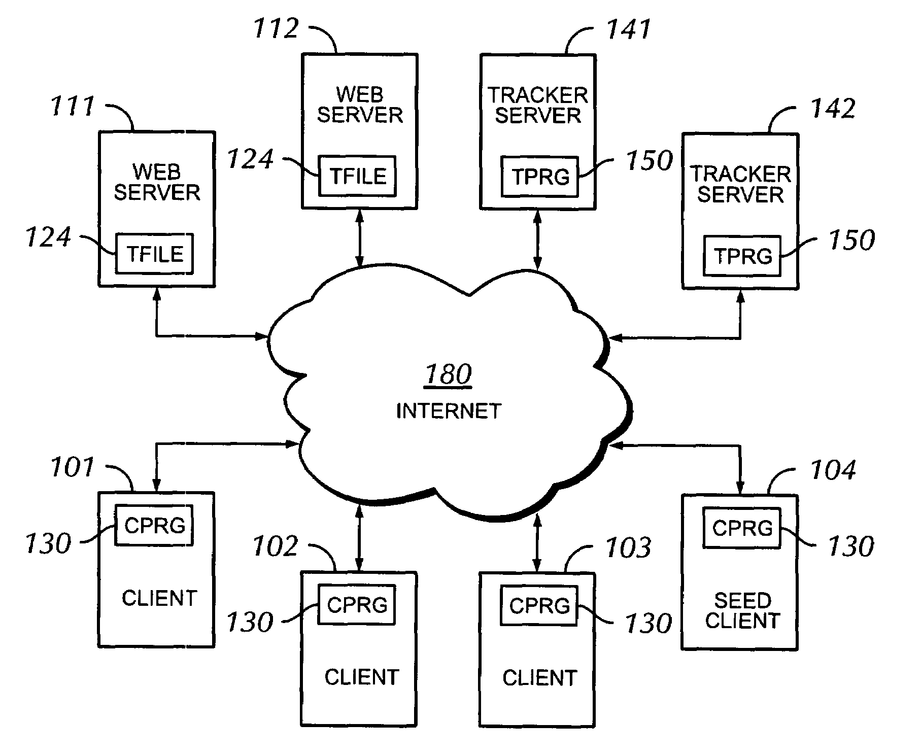
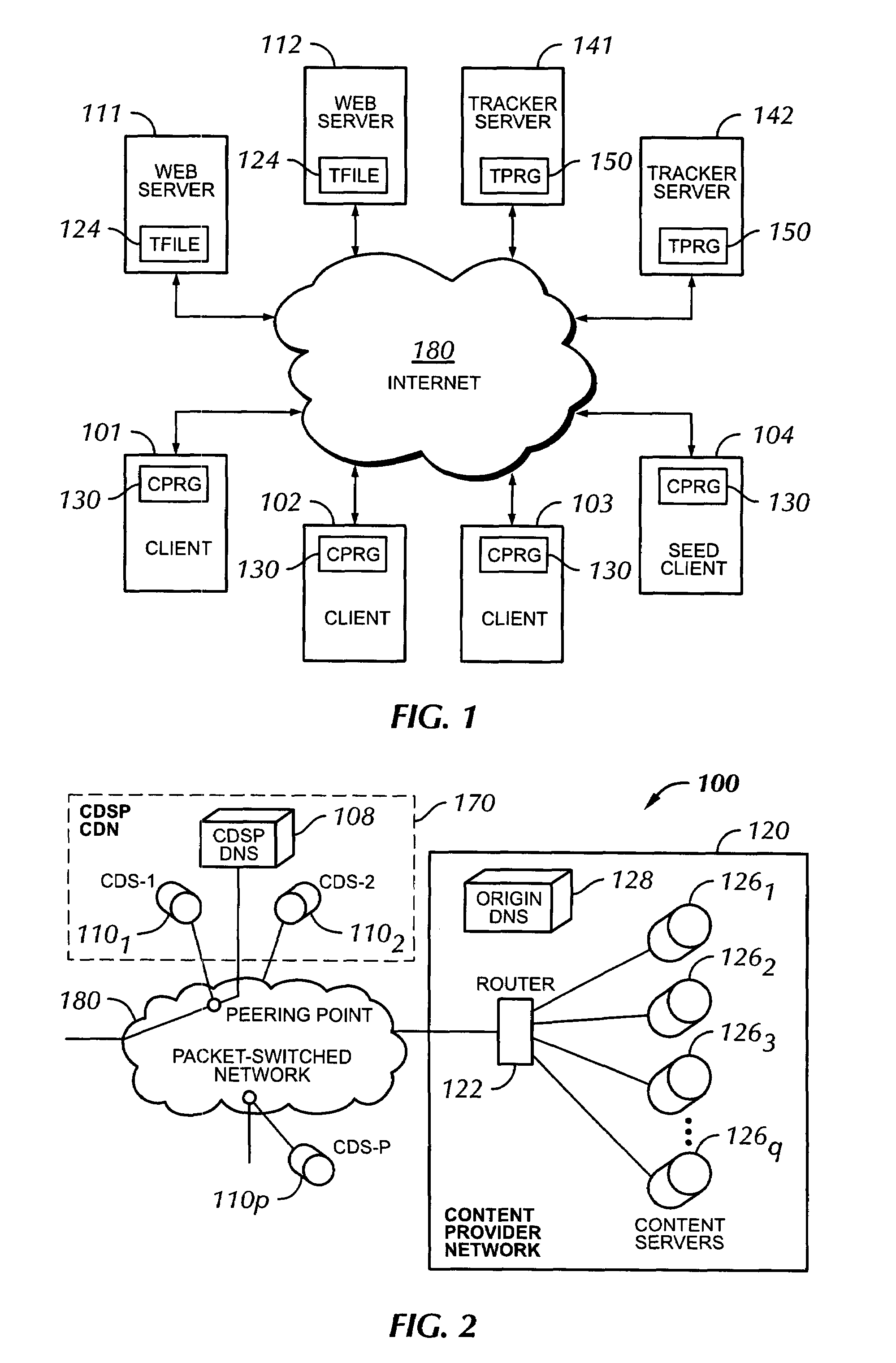
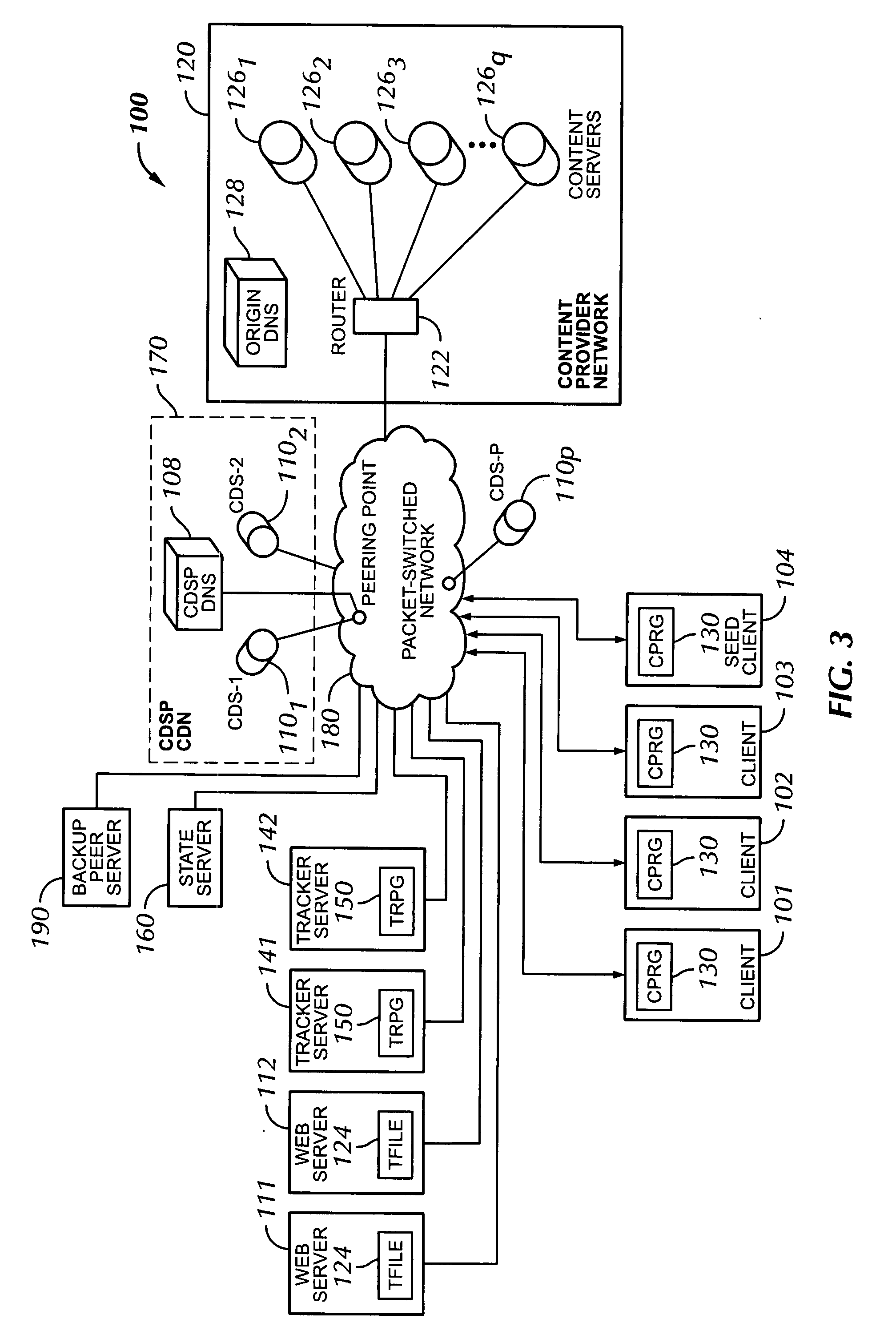
[0019]As described in more detail below, the present invention can employ both a client-server or content delivery network model and a peer-to-peer file transfer model to transfer content files from a content originator to multiple clients. The content file may be include, without limitation, data, video, audio, html pages and associated embedded objects, and any combinations thereof. In particular, the invention can dynamically choose which download model is most appropriate at any given time for any particular content file that a client wishes to download. Before describing various features of the invention in greater detail, a description of both a peer-to-peer network and a content delivery network will be presented. For clarity of discussion, the two models with be discussed separately with reference to FIGS. 1 and 2.

[0020]The most common method by which files are transferred on the Internet is the client-server model. A central server sends the entire file to each client that ...


PUM


Abstract

A method and apparatus is provided for delivering a content file to a client over a packet-switched network. The method begins by determining a suitable throughput required to deliver the content file to the client. Next, the throughput available in a peer-to-peer network for delivering the content file to the client is determined. The required throughput is compared to the available throughput. If the available throughput is less than the required throughput, the available throughput is supplemented with additional throughput. The content is then delivered to the client over the packet-switched network using the available throughput of the peer-to-peer network and the additional throughput.

Description


Claims


Application Information

Patent Timeline
IPC IPC(8): G06F15/16
CPCH04N7/17318H04N21/2402H04N21/44209H04N21/4622H04N21/632H04L67/1085H04L67/104H04L67/06H04L67/1091H04L67/322H04L67/108H04N21/8456H04L67/61
Inventor PAINTER, CHRISTOPHERLIN, FRANK LI-DEHWANG, PAULMILLER, TIMOTHY S.
Owner SONY CORP
Why Eureka
Try Eureka