Self-adjusting cam follower bracket for tufting machine

Inactive Publication Date: 2008-10-02
BREWER STEPHANIE
View PDF18 Cites 1 Cited by
  • Summary
  • Abstract
  • Description
  • Claims
  • Application Information

AI Technical Summary

Benefits of technology

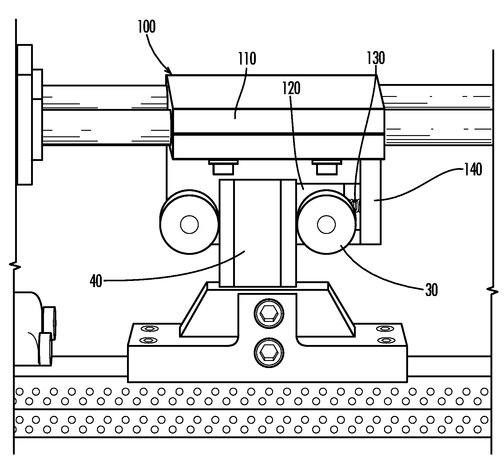
[0009]The present invention provides for a cam follower bracket that is used in conjunction with textile tufting machines. Typically, the present invention is employed in shifting tufting machines used to produce carpet and rugs. The cam follower bracket utilizes a floating lug design that self-regulates the amount of pressure that the cam follower bearings apply against the shifter block of the tufting machine. Because the bracket is able to self-regulate the pressure, the bracket lasts longer and does not need to be periodically monitored and / or tightened. Therefore, less user interaction is required and less machine downtime is needed when operating a tufting machine utilizing a bracket according to the present invention in comparison with known cam follower brackets.

Problems solved by technology

The amount of tufted goods that can be produced by any given machine is often limited by the speed of the tufting machine.
As the speeds of tufting machines have increased to over 2000 rpm, it has been discovered that many of the moving parts tend to wear increasingly fast, and additionally, it has been found that the needle bar can crack and break due to the excessive vibration caused by such high speeds.
Unfortunately, needle bars are very expensive to replace in terms of both money and machine downtime.
Furthermore, it has been found that vibration damage is even more likely to occur when a shifting needle bar arrangement is used to create patterns in the tufted goods.
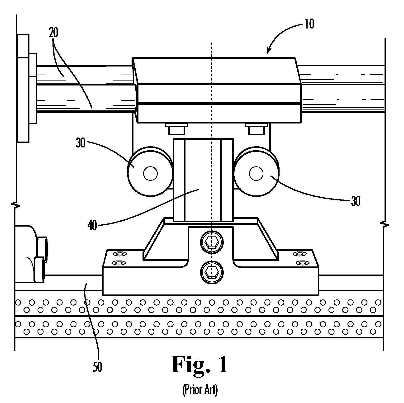
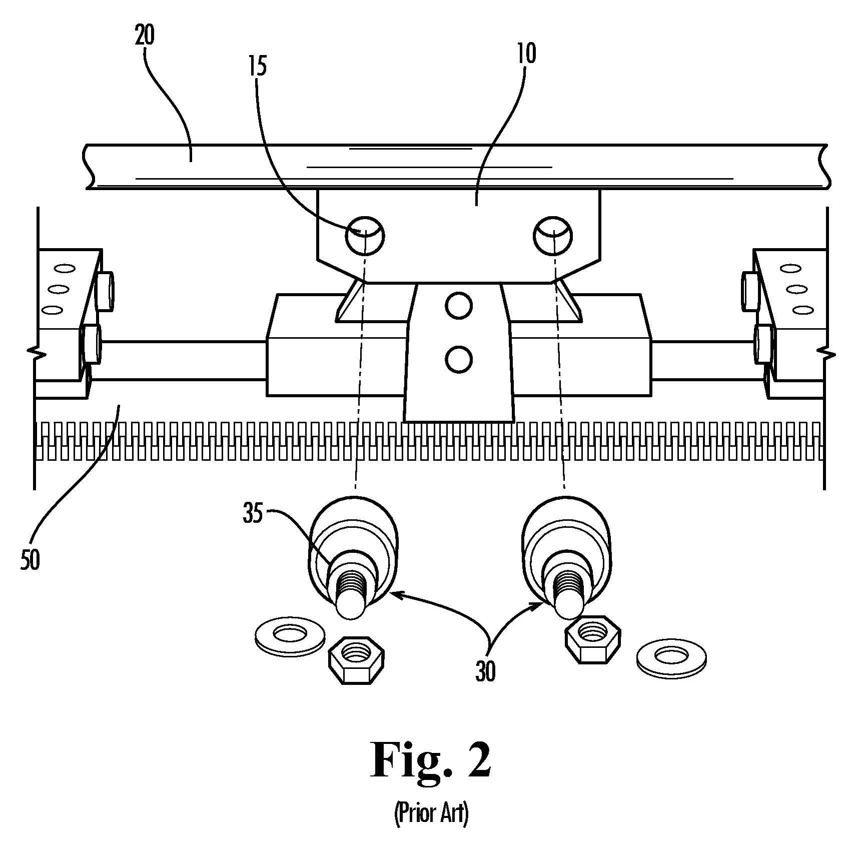
Over time however, the cam follower bearings 30 and shifter block 40 begin to wear.
Unfortunately, when a user utilizes either of the arrangements as discussed above, the user must continuously monitor the bearings' 30 configuration to make sure that the appropriate amount of force is being applied to the shifter block 40.
Too much pressure can cause the needle bar 50 to crack and break, while too little pressure can cause excessive needle bar vibration.
Additionally, neither of the aforementioned cam follower brackets 10 and 10′ are well suited for uneven bearing 30 and shifter block 40 wear, which is a very typical problem.
Presently, known brackets only permit one constant pressure, which can cause further uneven wear and damaging vibrations.

Method used


Image

  • Self-adjusting cam follower bracket for tufting machine
  • Self-adjusting cam follower bracket for tufting machine
  • Self-adjusting cam follower bracket for tufting machine

Examples


Embodiment Construction

[0021]The present invention may be understood more readily by reference to the following detailed description of the invention taken in connection with the accompanying drawing figures, which form a part of this disclosure. It is to be understood that this invention is not limited to the specific devices, methods, conditions or parameters described and / or shown herein, and that the terminology used herein is for the purpose of describing particular embodiments by way of example only and is not intended to be limiting of the claimed invention. Also, as used in the specification including the appended claims, the singular forms “a,”“an,” and “the” include the plural, and reference to a particular numerical value includes at least that particular value, unless the context clearly dictates otherwise. Ranges may be expressed herein as from “about” or “approximately” one particular value and / or to “about” or “approximately” another particular value. When such a range is expressed, another...


PUM


Abstract

The present invention provides a cam follower bracket that is used in conjunction with textile tufting machines. Typically, the present invention is used with shifting tufting machines used to produce carpet and rugs. The cam follower bracket utilizes a floating lug design that self-regulates the amount of pressure that the cam follower bearings apply against the shifter block of the tufting machine. Because the bracket is able to self-regulate the pressure, the bracket generally lasts longer and does not need to be periodically monitored and / or tightened. Therefore, less user interaction is required and less machine downtime is needed when operating a tufting machine utilizing a bracket according to the present invention in comparison with known cam follower brackets.

Description

CROSS-REFERENCE TO RELATED APPLICATION[0001]This application claims the benefit of U.S. Provisional Patent Application Ser. No. 60 / 908,830, filed Mar. 29, 2007, which is hereby incorporated herein by reference in its entirety for all purposes.TECHNICAL FIELD[0002]The present invention relates generally to the field of carpet tufting machines, and more particularly to cam follower brackets for carpet tufting machines.BACKGROUND OF THE INVENTION[0003]The use of tufting machines to create tufted materials, such as carpet and rugs, is well known in the art. The art of tufting incorporates a plurality of yarn carrying needles extending transversely across the machine. Conventional tufting machines use a reciprocating needle bar, which carries the plurality of needles. The needles are constructed and arranged to reciprocate cyclically beneath the needle bar to penetrate and insert pile into a backing material passing below the same in a longitudinal direction. During each penetration of t...

Claims


Application Information

Patent Timeline
IPC IPC(8): D05C15/30
CPCD05C15/14
Inventor BREWER, STEPHANIE
Owner BREWER STEPHANIE
Why Eureka
Try Eureka