Vehicle-use disc brake

Inactive Publication Date: 2008-10-02
HONDA MOTOR CO LTD
View PDF8 Cites 11 Cited by
  • Summary
  • Abstract
  • Description
  • Claims
  • Application Information

AI Technical Summary

Benefits of technology

[0007]It is an object of an embodiment of the present invention to provide a vehicle-use disc brake having an oil passage structure which can realize the miniatur

Problems solved by technology

However, depending on the oil passage structure which makes oil pressure chambers communicate with each other for operating the pistons which are interlocked on both sides of the brake disc, t

Method used


Image

  • Vehicle-use disc brake
  • Vehicle-use disc brake
  • Vehicle-use disc brake

Examples


Example

[0029]Hereinafter, a mode for carrying out the present invention is explained in conjunction with one embodiment of the present invention shown in the attached drawings.

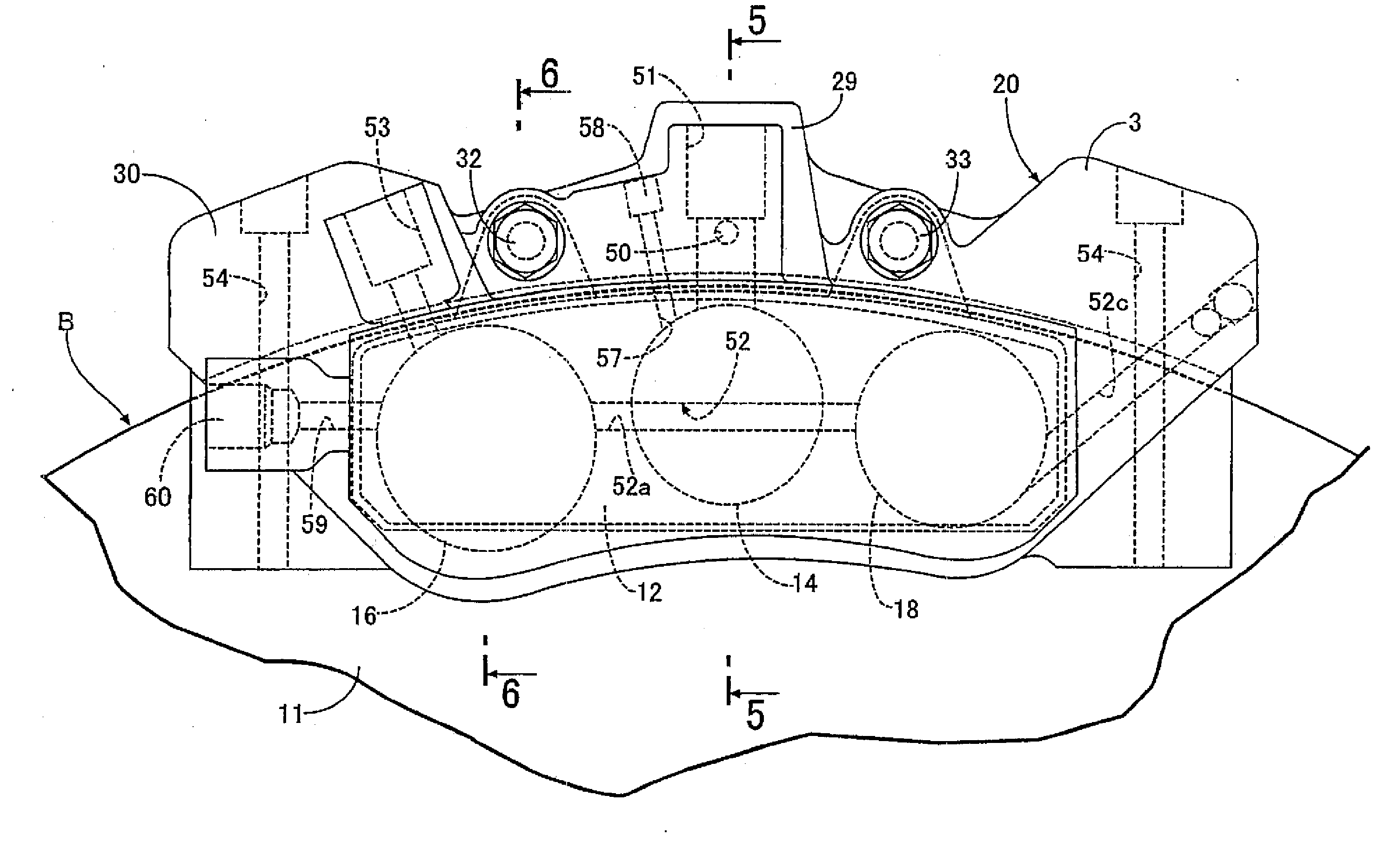
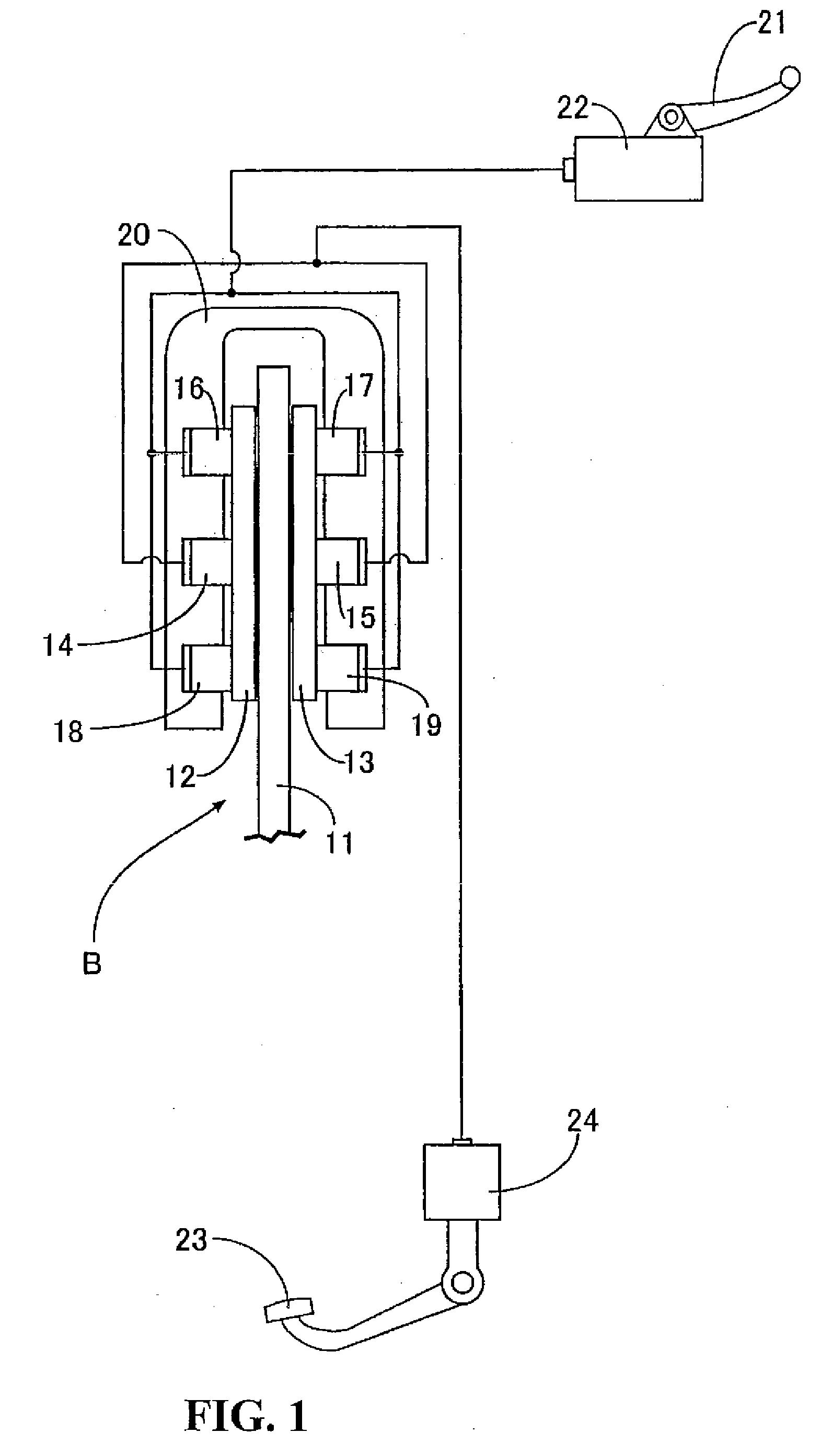
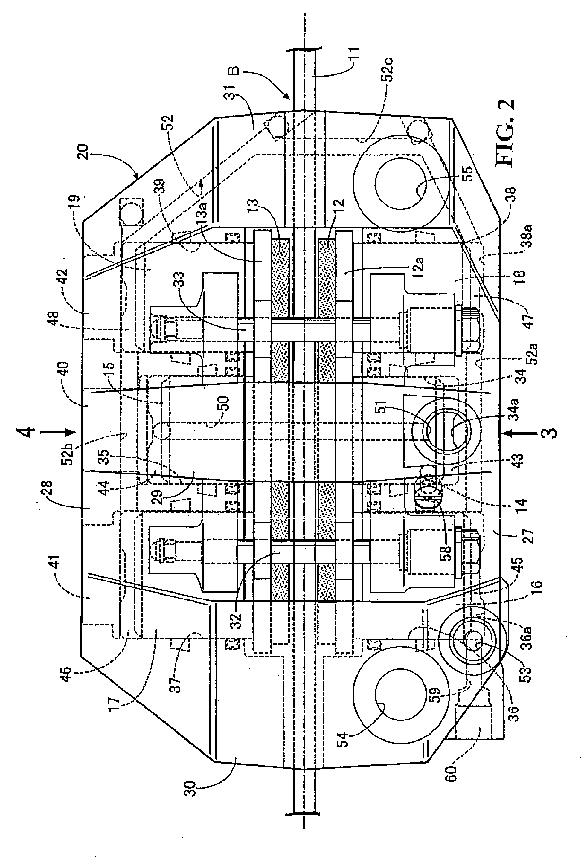
[0030]As illustrated in FIG. 1, a disc brake B according to the present invention is mounted on a front wheel (not shown in the drawing) of a motorcycle. The disc brake B includes a brake disc 11 which is rotatable with the front wheel, first and second pads 12, 13 which are arranged on both sides of the brake disc 11. A caliper body 20 is arranged astride the brake disc 11 with first, third and fifth pistons 14, 16, 18 which are capable of pushing the first pad 12 toward a brake-disc-11 side and second, fourth and sixth pistons 15, 17, 19 which are capable of pushing the second pad 13 toward the brake-disc-11 side are fitted slidably. When an oil pressure is outputted from a first master cylinder 22 which outputs the oil pressure in response to a manipulation of a brake lever 21 which constitutes a first brake manip...


PUM


Abstract

A disc brake in which three pistons are arranged respectively on both sides of a brake disc to miniaturize the disc brake and to enhance the merchantability of a motorcycle by simplifying the appearance shape of the disc brake. A first oil passage provides a communication with first and second oil pressure chambers respectively facing back surfaces of the first and second pistons. A second oil passage provides a communication with third, fourth, fifth and sixth oil pressure chambers respectively facing back surfaces of the third to sixth pistons. The first and second oil passages are formed inside of a caliper body.

Description

CROSS-REFERENCE TO RELATED APPLICATIONS[0001]The present application claims priority under 35 USC 119 to Japanese Patent Application No. 2007-081245 filed on Mar. 27, 2007 the entire contents of which are hereby incorporated by reference.BACKGROUND OF THE INVENTION[0002]1. Field of the Invention[0003]The present invention relates to a vehicle-use disc brake which includes a caliper body having first and second bodies which sandwich a pair of pads arranged on both sides of a brake disc rotated with a wheel between the first and second bodies and the brake disc. First and second pistons are capable of pushing both pads toward the brake-disc side and are fitted in the first and second bodies coaxially and slidably. Third and fourth pistons are capable of pushing both pads toward the brake-disc side and are fitted in the first and second bodies coaxially and slidably on one sides of the first and second pistons along the circumferential direction of the brake disc. Fifth and sixth pisto...

Claims


Application Information

Patent Timeline
IPC IPC(8): F16D65/14F16D65/18
CPCF16D55/228F16D2055/0016F16D2055/0091F16D2121/02F16D2123/00F16D2125/04
Inventor TOYODA, HIDETOSHI
Owner HONDA MOTOR CO LTD
Why Eureka
Try Eureka